Mold drawing design standards
Mold drawing design standards
1. Add the shrinkage dimensions to the plastic part drawing, mirror it, and then place it in the mold drawing to become the cavity drawing.
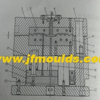
2. The mold drawing should clearly mark the mold reference and the plastic part reference, and indicate the dimensions of the distance from the mold center.
3. Determine whether each dimension of the mold is appropriate based on the size of the plastic part.
A. For the two-plate mold, the value of a is generally 45-70mm. If there is A slider, it is about 100mm.
b. For three-board molds, the value of A is generally 75-100mm. If there is a slider, it is around 150mm.
C. If the size of the plastic part is less than 150mm×150mm and c is less than 30mm, then the value of B is generally 15 to 25mm and that of D is generally 25 to 50mm.
If the size of the plastic part is 150mm×150mm, then the value of B is generally 25 to 50mm.
The value of e.D is generally C+ (2) to 40mm. The value of E: For dynamic templates, it is generally greater than 2D. The fixed template is generally slightly smaller than 2D.

Automobile parts mold Manufacturer in China (jfmoulds.com)
4. Confirm whether the plastic and shrinkage rate are correct. For some plastic parts, the shrinkage rates in different directions may not be the same. For plastic POM, the selection method of shrinkage rates is as follows: 2.2% for core mold, 1.8% for cavity, and 2.0% for parting surface and center distance.
5. The reference angles of the mold base and the inner mold inserts should be marked and in the same direction.
6. Whether the draft angles of the etched surface, transparent plastic part and the polished surface are reasonable. The general etched surface should be at least 1.5°, and the transparent plastic parts and the polished surface should be at least 3°.
7. The specifications and dimensions of the lifting ring screw holes for the formwork frame must be clearly indicated. For formwork frames with A width of over 450mm, lifting ring screw holes should be added to all four sides of the A and B boards.
Commodity Mould_Taizhou Jiefeng Mould Co.,Ltd. (jfmoulds.com)
8. The length of the screw, the depth of the screw hole and the specification should be indicated, and the serial number should be marked, such as S1, S2, etc.
9. The flow path of the cooling water holes should be clearly indicated. The optimal distance between the cooling water holes is 50mm, and it is best to be 15 to 20mm away from the parting surface or the plastic part. Pay attention to checking whether the O-ring seal of the water hole interferes with the push rod, screw and inclined top, etc.
10. The cooling water holes should be numbered, and their diameters and the threads of the water pipe joints should be marked, such as 1#IN, 1#OUT, 1/8PT, 1/4PT, etc.
11. Push rods, push tubes and flat push rods generally need to be at least 2.0mm away from the cavity edge (such as RIB). The arrangement of push rods should be as balanced as possible. The maximum diameter of push rods should not exceed 12mm. It is strictly forbidden to order non-standard push rods and push tubes (for example, for a BOSS column barrel of 6.03mm x $3.02mm, 6mmX 3mm should be ordered), except for customer requirements
12. The travel of the slider and the inclined top should be indicated, and it should be confirmed whether the travel is reasonable.
13. The content, position, size and depth (convex or concave) of the font on the plastic part must all be clearly indicated in the insert drawing.
14. In the DWG drawing file of the mold, the same type of line type should be represented by the same color, for example:
a. The center line uses No. 1 red (Center layer in sjgm.dwt);
b. Use light green No. 4 for the dotted line (unsee layer in sjgm.dwt);
c. Solid lines use size 7 white (the continuous layer in sjgm.dwt);
d. The cooling water channels uniformly use No. 5 green (pipe layer in sjgm.dwt);
e. The dimension lines should uniformly use blue size 3, and the text should use white size 7 (dim layer in sjgm.dwt).
f. The section lines uniformly use No. 8 gray (hatch layer in skg.dwt);
g. The insert line uses No. 6 purple (Imag layer in sjgm.dwt).
15. Technical requirements in the drawings
a. Technical requirements content and general sequence
a) Materials
b) Quantity
c) Heat treatment
d) Glue position marking
e)(Non-adhesive contact area) chamfering of the edge
"Explanation"
b. General Requirements
2) Technical requirements should be written in the lower left corner of the drawing and filled in from top to bottom.
b) The technical requirements must include at least three items a), b), and e) above. Items c), d), and f) are optional depending on specific needs. When parts are modified with standard components,
the material section should be marked with "STD" or "XX specification ××××(standard component code)".
16. Layer Management: Create different layers and place lines of different types of parts in separate layers. For instance, the dimension lines are placed within the dim layer, the cooling water lines within the cool layer, the push rod contour lines within the inject layer, the inner mold inserts within the insert layer, and the mold frame and other structural components within the mould layer, etc.
Related News
Calculation of injection mold forming dimensions
2025-10-10
Calculation of injection mold forming dimensionsI. Calculation Method for Genera...
The selection of mold base specifications and models
2025-09-28
The selection of mold base specifications and models(1) Selection of two-plate m...
Injection Mold Base Design (I)
2025-09-26
Injection Mold Base Design (I) The selection of the mold structure is of gr...
Exploring Injection Molds: The Cornerstone of Precision Manufacturing
2025-07-02
Exploring Injection Molds: The Cornerstone of Precision Manufacturing In the ...
The lateral core-pulling mechanism of
2025-10-19
The lateral core-pulling mechanism of "slider inclined guide column"I. Classific...
Solutions for air marks at the water outlet position of the mold and drag damage at the water outlet position of the battery frame
2025-08-27
Solutions for air marks at the water outlet position of the mold and drag damage...