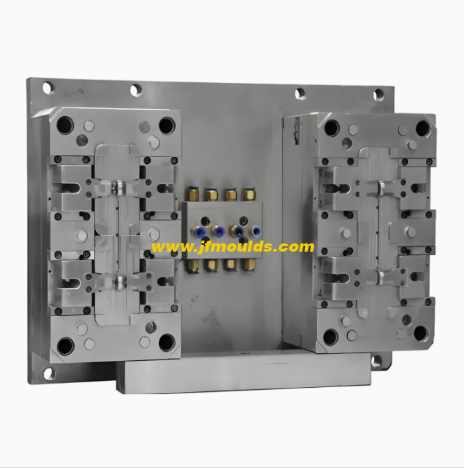
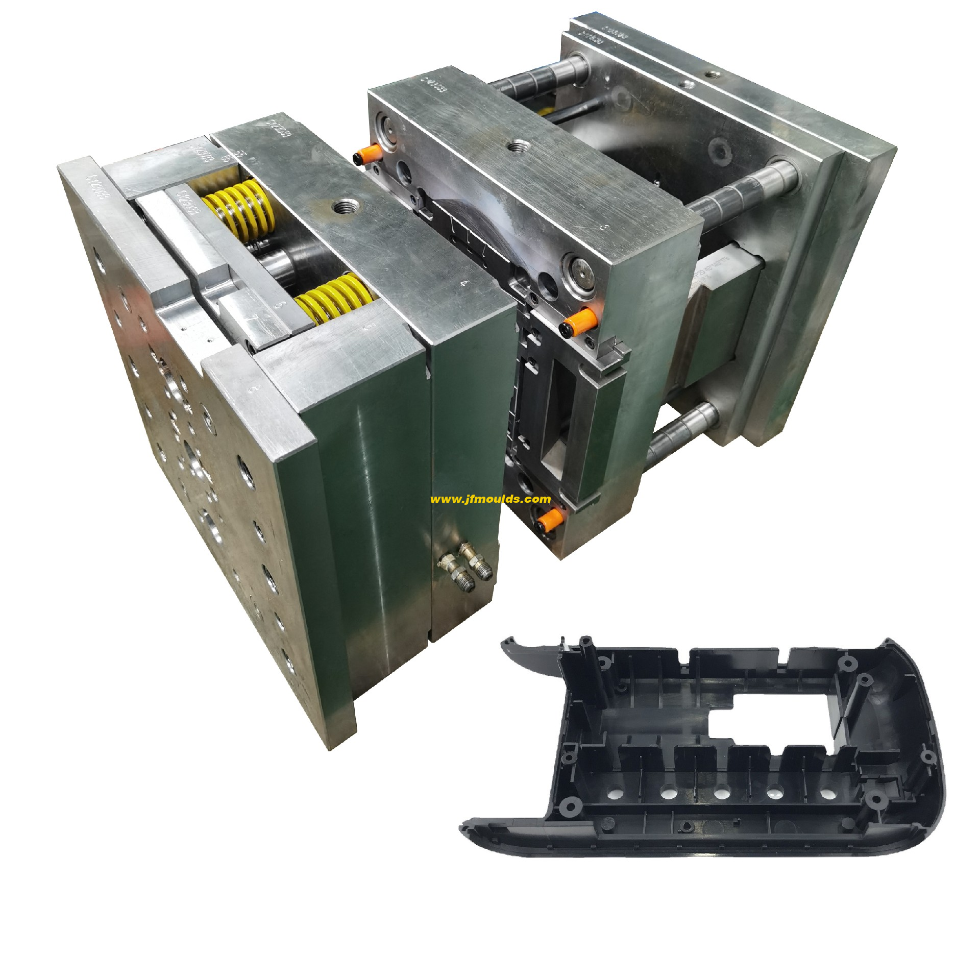
The lateral core-pulling mechanism of
The lateral core-pulling mechanism of "slider inclined guide column"
I. Classification of Lateral Typing and core-pulling Mechanisms
According to structural characteristics, lateral core-pulling mechanisms are classified into the following six major categories.
The lateral core-pulling mechanism of "slider inclined guide column ".
2. The lateral core-pulling mechanism of "slider bent pin ".
3. The lateral core-pulling mechanism of "slider T-shaped block ".
4. The lateral core-pulling mechanism of "slider hydraulic cylinder ".
5. Inclined top lateral core-pulling mechanism.
6. Lateral core-pulling mechanism of the inclined slider.
Two: The lateral side of "slider inclined guide column"
Design of inclined guide columns and inclined guide column pressure blocks

Bottle cap injection mold Manufacturer in China (jfmoulds.com)
Tilt Angle a
Under normal circumstances, for a=15° to 25°, the commonly used angles are 18° and 20° within this range. The smaller a is, the better, because the smaller a is, the smaller the torque that the inclined guide column bears, and the smaller the frictional force that the slider shoulder bears.
2. When the core-pulling distance is small and the slider is relatively high, the inclination Angle. Smaller values can be taken, but the minimum must not be less than 10°. When the core-pulling distance is large, the height dimension of the slider is small, and the clamping force of the plastic part on the lateral core-pulling is also small, the inclination Angle. A larger value can be taken, but the maximum cannot exceed 30°
The size of a depends on the distance of the lateral core-pulling and the height of the slider, and is independent of the ejection distance of the plastic part. Generally speaking, under the premise of meeting the lateral core-pulling distance requirements, the head of the inclined guide column should be as close as possible to the bottom surface of the slider. If the inclined guide column is too short and its head is far from the bottom surface of the slider, the slider will be subjected to a relatively large torque during core-pulling. This torque will increase the friction between the slider shoulder and the pressure block or T-slot, and at the very least, accelerate the wear of the friction surface. In severe cases, it may cause the slider to "get stuck" and prevent the core from being pulled out. Therefore, at the initial stage of core-pulling, the contact length between the inclined guide column and the slider hole should not be less than two-thirds of the length of the slider's inclined hole. On the contrary, if the inclined guide pins are too long and need to extend significantly beyond the bottom surface of the slider, as the core-pulling process proceeds, due to the increasing length of the lever arm, the torque borne by the inclined guide pins will become greater and greater, eventually leading to the bending and deformation of the inclined guide pins. If the height dimension of the slider is small due to a large core-pulling distance, the head of the inclined guide column must extend beyond the bottom surface of the slider. It is recommended that the extended length be less than one-third of the length of the inclined hole of the slider.

(2) Chamfer e at the head of the inclined guide column
e should be greater than or equal to the inclination Angle a of the inclined guide column to ensure that there is sufficient safety factor when the inclined guide column is inserted into the inclined hole of the slider. When a ≥18°, the head of the inclined guide column should avoid being semi-circular as much as possible.
(3) The length L of the inclined guide column can be calculated based on the basic formula of trigonometric functions :L=L1 L2=S/sina H/cosa
H Fixed plate thickness; S core-pulling distance; The inclination Angle of the inclined guide column.
Three: Slider and slider pressure Block Design
(1) Guidance of the slider
The following points should be noted when designing the slider
The slider operation should be smooth and safe, ensuring smooth lateral core-pulling without any jamming. The gap in the slide groove should be uniform, without any looseness or excessive tightness. The fit tolerance between the slider and the slide seat is H7/f7.
2. Oil grooves should be provided on the sliding surface of the large slider, and there must be cooling water channels
When the sliding stroke of the slider is too long, the guide groove must be extended on the mold base. Generally, the length of the sliding part should be about 1.5 times the height. When extracting the core, the length of the slider beyond the mold frame should not exceed one quarter of the slider's length; otherwise, the guide slide groove should be added
Long.
4. The wedge block of the slider must be inserted into the lower die for locking, with an insertion depth of 10 to 20mm and a locking Angle of 5° to 10°.
The design considerations for the slider pressure plate are as follows.
The material of the pressure plate is 718.
2. Surface ammonia infiltration treatment.
3-edge chamfer C1.
4. Processing oil grooves on sliding mating surfaces.
5. Selection of the pressure plate
a. Standard specifications should be given priority for the pressure plate, followed by the "7" shape
B. The upper end face of the pressure plate should be as flush as possible with the template surface to ensure the mold's aesthetic appearance
c. The pressure plate should be avoided from being pressed simultaneously on the inner mold inserts and the template as much as possible.
d. To prevent deformation, the length of the pressure plate should be controlled under 200mm as much as possible.
(2) Positioning of the slider during mold closing
1. General requirements for positioning
A. The positioning surface should be selected as a plane.
B. The positioning surface should be selected on relatively fixed parts, such as moving and fixed mold inserts, mold bases, etc., and must not be selected on sliders and movable inserts
c. When the slider is used for relative positioning, the slope of the positioning surface should be more than 5° on one side
d. The positioning requirements for the fixed mold slider are high because wire clamping can affect the appearance of the plastic part, so more attention should be paid. The positioning method is basically the same as that of the moving mold slider.
2. For individual sliders, the sliders shown in (a), (B ), and (c) have good positioning effects.
3. For the Haff slider (also known as the split slider). The following points should be noted when designing.
A. Each slider must have a reliable positioning. Generally, it is positioned by inserts. In cases where inserts cannot be used for positioning, separate positioning blocks should be adopted for positioning.
B. It is strictly prohibited to directly position the Haff slider with circular cores, push rods, push tubes or small inserts (these parts are prone to deformation under force).
c. There must also be a process positioning block between the two sliders to ensure that the plastic part does not grade at the wire clamping point.
d. It is essential to ensure that the inner mold inserts have sufficient positioning strength in the sliding direction.
e. The slider is not precisely positioned by directly using the arc surface of the moving mold insert. Therefore, a positioning block must be added to the insert (the positioning block is inserted into the mold base).
Commodity Mould_Taizhou Jiefeng Mould Co.,Ltd. (jfmoulds.com)
Related News
Solutions to the problems of column bending deformation, delamination, surface peeling and frequent pressing of small spouts in the mold
2025-08-18
Solutions to the problems of column bending deformation, delamination, surface p...
Design of Exhaust System for Injection Molds (1)
2025-10-14
Design of Exhaust System for Injection Molds (1)I. Reasons for setting up an exh...
The innovative design and intelligent development trend of injection molds
2025-07-09
The innovative design and intelligent development trend of injection molds In...
Calculation of injection mold forming dimensions
2025-10-10
Calculation of injection mold forming dimensionsI. Calculation Method for Genera...
Plastic properties and molding conditions
2025-09-13
Plastic properties and molding conditions Different plastics have different pr...
The solution to the problem of the lens length dimension of the mold being too large and the water line being clamped on the side of the middle hole position
2025-08-11
The solution to the problem of the lens length dimension of the mold being too l...


