The limit switch of the mold
The limit switch of the mold
In some cases, the actions of different mechanisms of the mold need to be carried out in sequence; otherwise, the mold will be damaged. To confirm whether the structural actions of the mold have been completed, limit switches need to be designed on the mold to convey the above information. Especially in molds where the push rod must be reset first, to ensure safety during the mold production process, a limit switch must be added. Only when the push plate is completely reset and the limit switch is triggered will the mold start the next action.
1. Common models of limit switches
Automobile door panel mold Manufacturer in China (jfmoulds.com)
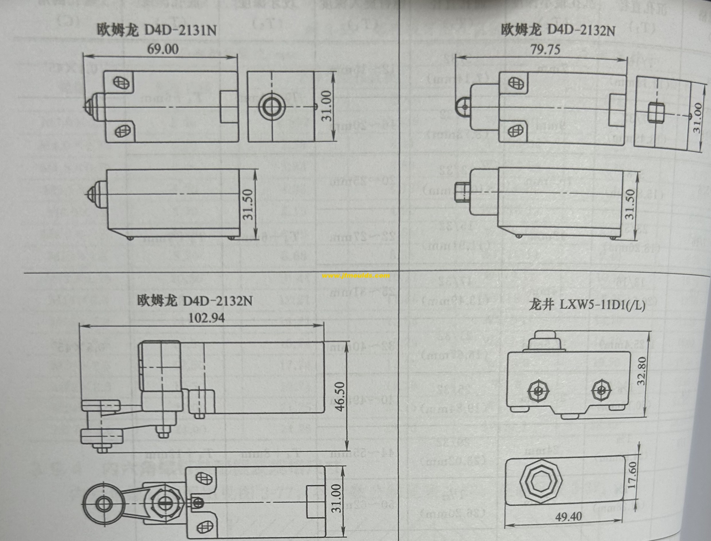
2. Assembly method of limit switches
Different limit switches have different functions and their assembly methods are also not the same.
Hydraulic core-pulling limit travel switch for oil cylinder
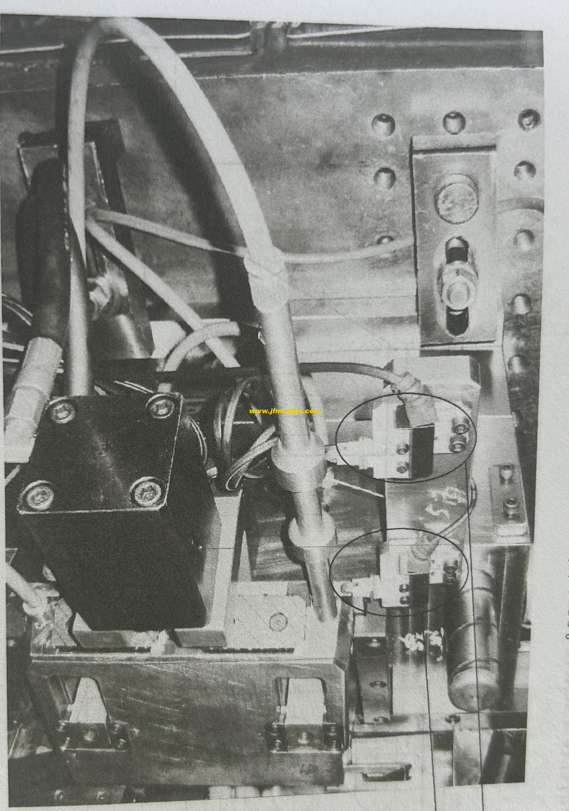
When the hydraulic pressure of the cylinder clearance drives the slider to pull the core, to confirm whether the slider has moved in place and avoid damaging the mold, a limit switch should be installed for protection. Generally speaking, there are two forms of sliders for cylinder core-pulling: the slider is inside the template; The slider extends beyond the template or is level with it.
Installation principle of limit switch: The limit switch is installed on an adjustable seat plate, which is fixed on the template. A baffle is designed to be fixed on the slider. In this way, when the slider moves, it drives the baffle to come into contact with the limit switch, thereby achieving the limiting effect. Due to the diverse specific structures of sliders, the installation methods of limit switches also vary.
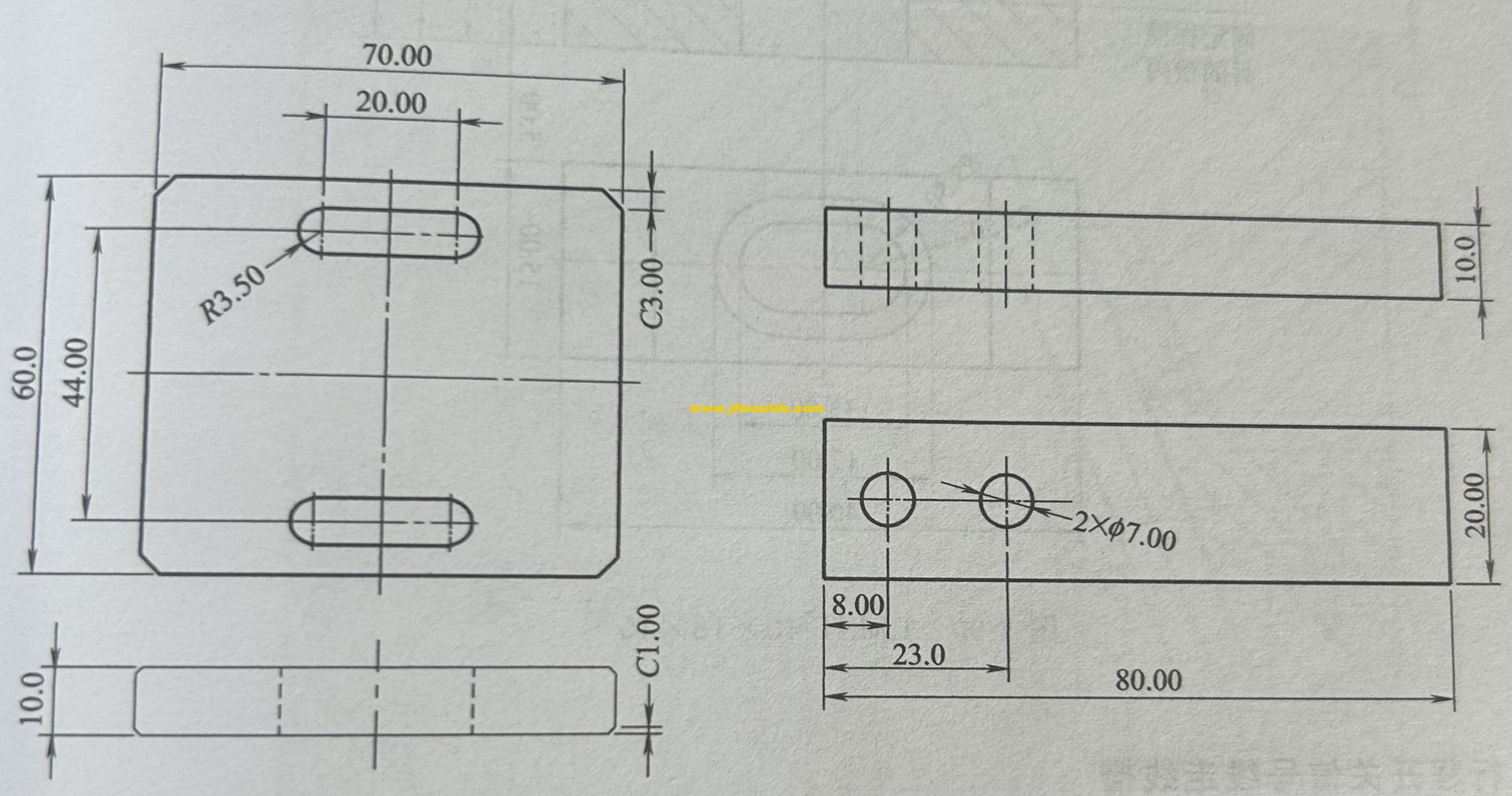
Model of limit switch fixed plate
The fixed plates of all limit switches can use the standard blocks shown: LMSB-60×70×10, made of 45 steel.
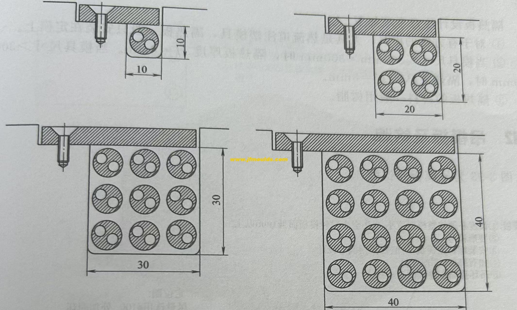
The limit switch signal line runs through the trunking
The design cross-section of the signal wiring harness for each limit switch is a 10mm×10mm trunking. The design cross-section of the signal wiring harness for n limit switches is n×10mm×10mm. The cross-section can be square or rectangular. Rounded corners should be designed in the turning areas or exits of the trunking to prevent sharp corners from cutting the wires.
Limit switch signal line socket
The socket for the limit switch signal line is installed on the upper half of the non-operating side. If the customer has special requirements, it will be designed according to the customer's requirements.
Auto Mould_Taizhou Jiefeng Mould Co.,Ltd. (jfmoulds.com)
Related News
The "Shaping Master" Hidden in Daily Necessities
2025-07-17
The "Shaping Master" Hidden in Daily Necessities In today's industrial produc...
Wire clamping and air marks near the screw holes of the mold
2025-08-02
Wire clamping and air marks near the screw holes of the mold Phenomenon: Wire...
The structure, materials and design of injection molds
2025-07-18
The structure, materials and design of injection molds In the vast landscape ...
Injection molds: The "Industrial Gene" Hidden Behind Everything
2025-07-12
Injection molds: The "Industrial Gene" Hidden Behind Everything When our fing...
The general process of mold design and drawing
2025-09-08
The general process of mold design and drawingOne: Organize and inspect customer...
The cavity arrangement and parting surface of the mold
2025-10-09
The cavity arrangement and parting surface of the mold Forming parts refer ...
