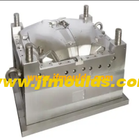
The cavity arrangement and parting surface of the mold
The cavity arrangement and parting surface of the mold
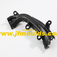
Forming parts refer to mold parts that directly participate in the formation of the cavity space, such as the return die (cavity), punch (core), piece, lateral core-pulling, etc. When designing molded parts, full consideration should be given to the plastic's molding shrinkage rate, demolding slope, and the processability for manufacturing and maintenance.
The design of formed parts can generally be carried out in the following steps
① Determine the number of mold cavities
② Determine the position of the cavity.
③ Determine the parting line of the plastic part and the parting surface of the mold
④ When lateral core-pulling is required, design a lateral core-pulling mechanism.
⑤ Determine the forming dimensions of the core cavity and the draft Angle
⑥ Determine the combination and fixation methods of the formed parts
Stool mold Manufacturer in China (jfmoulds.com)
Determine the number of cavities
If the injection molding machine that matches the mold has been determined in advance, the number of cavities can be determined in the following two ways
(1) According to the rated injection volume of the injection machine used
(Total weight of plastic parts in each cavity + concrete in the gating system) 80% of the rated injection volume of the injection machine
(2) According to the rated clamping force of the injection machine
Assuming the sum of the projected areas of each cavity and the runner on the parting surface is S part (mm ²), the rated clamping force of the injection machine is F part, and the average pressure of the plastic melt on the cavity is type, then
S Household type F lock x 80%
One: Cavity alignment
The principle of ranking
① The principle of the shortest flow channel: Reduce the solidified material in the gating system, and save the cost of steel and mold manufacturing.
② Temperature balance principle: Ensure that the temperatures in all parts of the mold cavity are approximately equal to guarantee that the shrinkage rates of the plastic parts in each cavity are the same.
③ Pressure balance principle: Ensure that the resultant force of the tensile force that the mold bears during injection is close to the center of the mold and in a straight line with the clamping force of the injection molding machine.
④ Feeding balance principle: For molds with multiple cavities in one mold, the same plastic part should be fed from the same position to ensure the interchangeability of the plastic parts. The size and length of the runner and gate should be adapted to the size of the plastic part, and it is necessary to ensure that all cavities are fed and filled simultaneously as much as possible.
Precautions for the arrangement of molds with multiple cavities in one mold.
Larger or more complex plastic parts should be placed near the main runner, that is, the gate sleeve. However, the cavity should not be arranged within a diameter of 30mm around the gate sleeve as much as possible, or the steel thickness from the cavity to the gate sleeve should be at least 8mm.
For molds with multiple cavities in one mold, the steel thickness A between each cavity and the steel thickness B from the cavity to the edge of the inner mold insert can be selected based on the cavity depth. The deeper the cavity, the thicker the steel thickness should be.
Special circumstances include:
When a concealed gate is used, there should be sufficient space for the concealed gate and the position for arranging the push rods
b. When the plastic part is large in size and the cavity is deep (60mm)
c. The size of the plastic part is relatively large, and the inner model core is inlaid through. At this point, the insert forms a frame structure 1 with poor rigidity. The steel thickness should be increased to enhance rigidity.
When cooling water needs to be passed between the cavities, the distance between the cavities should be larger to ensure that the steel thickness between the cavities and the cooling water channels is no less than twice the diameter of the water channels.
Sure enough, when the mold needs to be core-pulled from the side, the sequence should give priority to core-pulling from the left and right sides, and try to avoid core-pulling up and down.

Two: Parting surface
The main contents of parting surface design
The main contents of parting surface design are as follows.
① Position of the parting surface: Which part is formed by the moving mold and which part is formed by the fixed mold.
② Shape of the parting surface: Is it a plane, an inclined surface, a stepped surface or an arc surface
③ Positioning of the parting surface: How to ensure the positional accuracy of the core and cavity, and ultimately guarantee the dimensional accuracy of the plastic part
2. General principles for the design of parting surface positions
(1) The principle of aesthetic appearance
The selection of the parting surface should minimize its impact on the appearance of the plastic part. Especially for plastic parts with clear requirements for appearance, more attention should be paid to the influence of the parting surface on the appearance
(2) The principle of convenient processing
The selection of the parting surface should make the mold structure simple and easy to process, especially for the processing of the core and cavity.
(3) The principle of easy molding
The selection of the parting surface should be conducive to the pouring of the melt, the venting of the cavity and the design of the cooling system. Usually, when designing the parting surface, designers often encounter problems where there are more than two demolding directions on the plastic part.
For the shorter stroke demolding direction, the slider is used for lateral core-pulling. However, when the lateral core-pulling mechanism closes the mold, the clamping force it can provide is relatively small. If the projected area of the plastic part in this direction is large, problems will occur. For molds with inserts, the simplicity and convenience of insert installation should also be taken into consideration.
(4) Smooth demolding principle
The selection of the parting surface is conducive to the demolding of the plastic part, ensuring that the plastic part remains on the side with the ejection mechanism during mold opening (sometimes it is.
(Moving mold, sometimes fixed mold.)

Three: Shape design of the parting surface
The shape of the parting surface is best when it is a plane perpendicular to the mold opening direction, followed by inclined surfaces, then smooth arcs, stepped surfaces, etc. The parting surface shall not have sharp corners or edges. Sharp corners and edges will make processing more difficult and also affect the sealing material of the parting surface and the service life of the mold.
(1) Step parting surface
There are multiple options for the parting surface of this plastic part, and the final choice often depends on the customer's requirements.
(2) Inclined parting surface
The inclined parting surface should be equipped with a stop mouth positioning surface to counteract the horizontal component of the expansion force. The positioning surface is determined based on the actual situation and can be on either side. Both (a) and (b) are acceptable. The inclination Angle of the positioning surface. It is generally 10 "to 15". The greater the slope, the worse the positioning effect. The inclined parting surface should extend outward by 5 to 10mm according to the Angle of the parting surface to prevent the edge of the cavity from cracking and to avoid movement during the FIT mold.
(3) Curved surface parting surface
The design of the curved surface parting surface is roughly the same as that of the inclined surface parting surface. In the figure, A=5 to 10mm, and the inclination Angle ea is generally 10 to 15°
(4) The parting surface that is rubbed through or bumped through on the side
If the threading as shown in Figure 4-5(b) is adopted, the formed plastic part has no wire clamping, as shown in Figure 4-5(d), but the plastic part is prone to flash, and the flash is balanced with the side hole, reducing the size of the hole. When rubbing through, it is best to have a slope of 3 or more on the side. If the piercing method is adopted, the plastic part can see the wire clamping, but it is not easy to have flash. Even if there is flash and it is perpendicular to the hole, it does not affect the size of the hole. a is taken as 6°-10°. If c is chosen, it can be suggested that the customer make a slope of 3° to 5° on each side of the bump hole, so that there will be no wire clamping.
(5) The parting surface of the inclined square hole
The inclined square hole should be given priority for penetration. The condition for penetration is that if a<1° in the figure, the lateral core-pulling a 3° should be given priority.
(6) There is a raised parting surface on the side
There is a raised structure on the side. The parting surface should be prioritized for lifting, but this will cause wire clamping. Moreover, since the draft angles of the moving and fixed molds are exactly opposite, the wire clamping on both sides will have obvious lifting, affecting the appearance. If the customer cannot accept it, only lateral core-pulling can be adopted.
(7) Piercing and rubbing through on the parting surface
"Piercing through" refers to the contact surface of the moving and fixed mold forming parts being perpendicular to or roughly perpendicular to the mold opening direction; otherwise, it is called "rubbing through". When the contact surface is parallel to or approximately parallel to the mold opening direction, it is also called penetration. From the perspective of the convenience of mold manufacturing, the sealing surface on the parting surface should be pierced by impact as much as possible to avoid being rubbed through. Except for round holes which can be pierced by insertion, insertion is generally prohibited for non-round holes. When there are large through holes on the plastic part and the impact penetration surface on the mold is large, the middle of the impact penetration surface should be left empty to reduce the impact penetration area and facilitate the FIT mold.
Commodity Mould_Taizhou Jiefeng Mould Co.,Ltd. (jfmoulds.com)
Four: Positioning of the parting surface
The guide pins and guide sleeves of the moving and fixed molds are clearance fits. They mainly serve to guide. The positional accuracy of the formed parts must be guaranteed during the design of the parting surface. If the plastic part is complex and the parting surface is inclined or curved, the shape and size of the sealing surface, how to position it, and there must be a measurement reference when designing the parting surface must be taken into consideration.
Even for planar parting surfaces or stepped parting surfaces, in order to improve accuracy, conical surface positioning is sometimes designed on the parting surface.

Related News
Check the thickness of the wall
2025-09-17
Check the thickness of the wallThe principles for designing the wall thickness o...
The causes and solutions of bubbles, mold sticking and gate sticking in injection molded products
2025-07-31
The causes and solutions of bubbles, mold sticking and gate sticking in injectio...

Solutions to the problem of easy breakage at the junction of the mold's appearance color difference and material flow
2025-09-05
Solutions to the problem of easy breakage at the junction of the mold's appearan...
The key to plastic product molding
2025-07-21
The key to plastic product moldingBehind today's dazzling world of plastic produ...
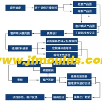
A collection of mold manufacturing processes, standards, processes and cases.
2025-06-19
The process flow chart is as follows: all kinds of tools and products used in ou...

Define a new paradigm for the injection mold industry through technological breakthroughs and ecological reconstruction
2025-07-04
Define a new paradigm for the injection mold industry through technological brea...