Design of Exhaust System for Injection Molds (1)
Design of Exhaust System for Injection Molds (1)
I. Reasons for setting up an exhaust system in injection Molds
The gases in injection molds not only include the air in the cavity, but also the air in the runner, the decomposition gases produced by the plastic melt, and the water vapor turned from the moisture in the plastic at high temperatures. During injection molding, all these gases should be discharged in a timely manner; otherwise, the following hazards will occur.
① Defects such as flow marks, water splashes and weld marks are formed on the surface of the plastic part.
② Defects such as bubbles and loose structure may occur inside the plastic part, and in severe cases, it may lead to incomplete filling.
③ It is difficult to fill the melt or flash occurs locally.
④ Under high temperature and high pressure, the gas generates high temperature, causing local carbonization and charring marks on the products.
⑤ Reduce the filling speed of the melt.
When the injection speed is reduced, not only is the molding cycle prolonged, but the melt temperature also drops rapidly. If the injection pressure is increased at this time, the residual stress will increase accordingly, and the possibility of warping deformation of the plastic part after demolding will increase. If the material temperature is raised to reduce the injection pressure, it will cause the plastic to crack again.
Appropriately setting up exhaust channels can significantly reduce injection pressure, shorten injection time and holding time, as well as decrease clamping pressure, thereby enhancing production efficiency, lowering production costs and reducing the energy consumption of the machine.
For transparent plastic parts or those with strict surface requirements, special attention should be paid to the design of the mold exhaust system.
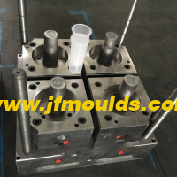
Cup injection mold Manufacturer in China (jfmoulds.com)

Two: The location of trapped gas in the cavity
The location of trapped gas in the cavity is usually at the following places
① Thin-walled structural cavity, the end of melt flow.
② The junction of two or more melts.
③ The place where the melt finally reaches in the cavity.
④ The bottom of the cavity hole in the mold is mostly the end of the solid column position in the product.
⑤ The bottom of the reinforcing ribs and screw columns of the formed products.
⑥ Dead corners of complex mold cavities
Special Note
The exact position of the exhaust slot should be determined only after the mold trial. It is strictly forbidden to assume that the exhaust slot should be opened before the mold trial
Three: Exhaust methods for injection molds
The venting in this chapter refers to the venting of the cavity and the gating system. The venting methods in injection molds include the following types:
① Parting surface (including exhaust grooves)
② Mating surfaces of inserts.
③ The mating surface between the push rod or push tube and the inner mold insert.
④ Exhaust from the side core-pulling mechanism.
⑤ Add an exhaust needle or insert at the trapped air point to release the air.
⑥ Breathable steel exhaust.
⑦ Exhaust through the air valve.

Four: Design Principles of Exhaust System
The exhaust slot can only allow gas to be discharged but not the plastic melt to flow out.
② Different plastics have different depths of exhaust grooves due to their varying viscosities.
③ The cavity should be designed with exhaust slots, and the runner and cold material cavity should also be designed with exhaust slots to minimize the amount of gas in the gating system entering the mold cavity.
④ The exhaust slot must extend outside the mold base, especially when exhausting through inserts, exhaust pins or exhaust inserts. Special attention should be paid.
⑤ The exhaust groove should be processed by a milling machine as much as possible. After processing, it should be polished with 320-grit sandpaper to remove the tool marks. The exhaust groove should avoid being processed by a bed or a grinding machine. The surface processed by a grinding machine is too flat and smooth, and the exhaust effect is often poor.
The exhaust grooves on the parting surface should be set on one side of the cavity, usually on the fixed mold insert.
A 45° chamfer should be machined on both sides of the exhaust groove.

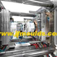
Commodity Mould_Taizhou Jiefeng Mould Co.,Ltd. (jfmoulds.com)
Related News
Design of Exhaust System for Injection Molds (1)
2025-10-14
Design of Exhaust System for Injection Molds (1)I. Reasons for setting up an exh...
In-depth Analysis of Injection Molds: A Full-Process Exploration from Design to Application
2025-07-10
In-depth Analysis of Injection Molds: A Full-Process Exploration from Design to ...
Injection mold industry: Breaking through technological barriers and seizing the new track of intelligent manufacturing
2025-07-01
Injection mold industry: Breaking through technological barriers and seizing the...
Limit pins and springs of the mold
2025-10-04
Limit pins and springs of the moldOne: Limit pinThe function of the limit nail i...
How to solve the problems of whitening, charring and deformation of the bone position at the water outlet of the mold
2025-08-16
How to solve the problems of whitening, charring and deformation of the bone pos...
Exploring Injection Molds: Unlocking the Core Code of Plastic Molding
2025-07-10
Exploring Injection Molds: Unlocking the Core Code of Plastic Molding In the ...