Check the thickness of the wall
Check the thickness of the wall
The principles for designing the wall thickness of plastic parts are as follows.
Uniform wall thickness is the first principle in the design of plastic parts. It can ensure uniform filling and cooling shrinkage, good molding, high dimensional accuracy and high productivity. If the wall thickness cannot be uniform due to certain special requirements of the plastic part, a bevel should be used to gradually transition between the thick and thin walls. In addition, the ratio of thickness to thinness must be strictly controlled to the following ratio.
Thermoplastic: Compression 1:3, extrusion 1:5.
Thermoplastic plastics: Injection molding 1:(1.5-2).
2. Under the condition of meeting the structural and usage requirements of the plastic part, the wall thickness should be as small as possible: the mold cools down quickly, the plastic part is light in weight, and plastic is saved.
3. The design of the wall thickness of the plastic part should be able to withstand the impact and vibration of the ejection device, etc.

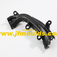
Automobile bumper mold Manufacturer in China (jfmoulds.com)
4. At the connection and fastening points of plastic parts, the embedding points of inserts, and the convergence (weld lines) of plastic melts in holes and Windows, there must be sufficient thickness.
5. When determining the wall thickness, the required strength during storage and handling must be taken into consideration
6. The wall thickness required for melt filling during molding should be met. It is necessary to avoid thin walls with insufficient filling or prone to charring, as well as thick walls with melt cracking or prone to depressions.
Two: Strengthen the tendons
Reinforcing ribs are indispensable functional structures on plastic parts. Reinforcing ribs can effectively enhance the rigidity and strength of plastic parts like "I" shaped steel without significantly increasing the wall thickness of the plastic part. However, they do not have the inverted surface that is difficult to form like "I" shaped steel. They are particularly suitable for plastic parts that are frequently subjected to pressure, torque, and bending. In addition, the reinforcing ribs can also serve as internal channels, which is conducive to the filling of the body and is of great help in the forming of complex and large components.
Reinforcing ribs are generally designed on the non-surface of the plastic part, and their direction should be as consistent as possible with the flow direction of the melt. The reinforcing ribs should not be too long or too thick, otherwise it will increase the difficulty of injection molding, such as air tightness and shrinkage and depression on the back.
Three: Rounded corners
The two intersecting planes of the plastic part should transition with arcs as much as possible. The functions are as follows.
1. Disperse the load, enhance and fully exert the mechanical strength of the plastic part.
2. Improve the fluidity of the plastic melt, facilitate filling and demolding, and eliminate defects such as depressions at the corners of the walls.
3. It facilitates the mechanical processing and heat treatment of the mold, thereby increasing the service life of the mold.
4. Stress concentration is prone to occur at sharp corners, which can cause local cracking in molds and plastic parts.
Four: Forced demolding
Plastic parts are often formed by taking advantage of the elastic deformation of plastics and the small depth dimensions of the convex and concave parts to forcibly push the plastic parts out of the mold.
Commodity Mould_Taizhou Jiefeng Mould Co.,Ltd. (jfmoulds.com)
Gear
Five: The shape and size of plastic gears
The basic parameters of plastic gears and their calculation formulas are as follows.
The total number of teeth of a gear
Meaning of tooth number:
Module m: Module is an important parameter for manufacturing gears. For two meshing gear molds
The numbers must be equal.
m=p/n d=mx
Tooth profile Angle. The radial diameter and tooth profile at the intersection of the tooth profile curve and the pitch circle
The acute Angle formed by the tangent at this point.
Transmission ratio i: i=n1/n2
Center distance a: a= (d1+d2) /2
Tooth top height :ha=m
Root height: hf=1.25m
Tooth height: h=2.25m
Diameter of the dividing circle :d=mx
Diameter of the tooth tip circle :da=m(x+2)
Diameter of the root circle :dr=m(x-2.5)
Related News
Performance characteristics and selection criteria of injection molds
2025-06-30
Performance characteristics and selection criteria of injection molds This ...

The grooves of the mold's injection air inlet, the surface light and shadow, the scratches on the grooves and the size of the screw holes have increased
2025-08-13
The grooves of the mold's injection air inlet, the surface light and shadow, the...
Solutions to the problems of air streaks, exposed glass fibers and charring in molds
2025-08-21
Solutions to the problems of air streaks, exposed glass fibers and charring in m...
Solutions to problems such as poor transparency, unstable dimensions, spots, and black lines in injection molded products
2025-07-31
Solutions to problems such as poor transparency, unstable dimensions, spots, and...
Check the thickness of the wall
2025-09-17
Check the thickness of the wallThe principles for designing the wall thickness o...
Exploring Injection Molds: A Comprehensive Analysis from Design to Application
2025-07-08
Exploring Injection Molds: A Comprehensive Analysis from Design to Application ...