A collection of mold manufacturing processes, standards, processes and cases.
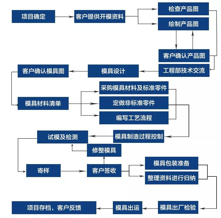
The process flow diagram is as follows:
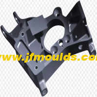
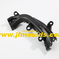
All kinds of tools and products used in our daily production and life, from the base of the machine tool and the body shell to the shell of an embryo head screw, button and various household appliances, are closely related to the mold. The shape of the mold determines the shape of these products, and the quality and accuracy of the mold also determines the quality of these products. Because of the different materials, appearance, specifications and uses of various products, the molds are divided into non-plastic molds such as casting molds, forging molds, die-casting molds, stamping molds, and plastic molds.
In recent years, with the rapid development of the plastics industry and the continuous improvement of the strength and precision of general and engineering plastics, the application range of plastic products is also expanding, such as: household appliances, instrumentation, construction equipment, automobile industry, daily hardware and many other fields, the proportion of plastic products is increasing rapidly. A well-designed plastic part can often replace multiple traditional metal parts. The trend of plasticization of industrial products and daily products is on the rise.
1, the general definition of the mold: in industrial production, with a variety of presses and special tools mounted on the press, through the pressure of metal or non-metallic materials to produce the desired shape of parts or products, this special tool is collectively referred to as the mold.
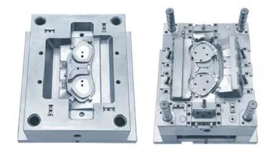
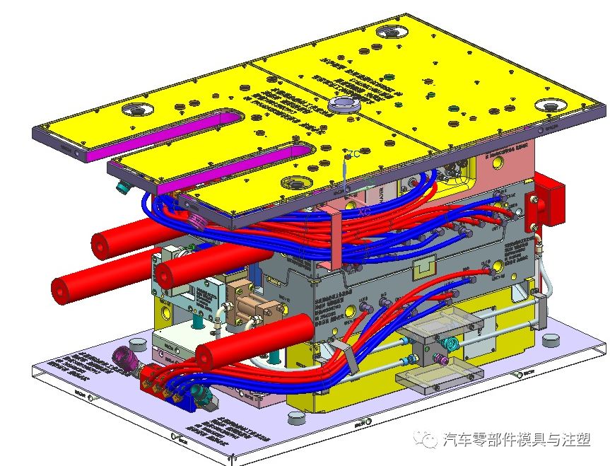
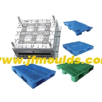
2, injection molding process description: mold is a tool for the production of plastic products. It consists of several sets of parts, this combination has a molding cavity. During injection molding, the mold is clamped on the injection molding machine, molten plastic is injected into the molding cavity, and cooled and shaped in the cavity. Then the upper and lower molds are separated, and the products are ejected from the mold cavity and left the mold through the ejection system. Finally, the mold is closed again for the next injection molding. The whole injection molding process is carried out circularly.
3, the general classification of mold: can be divided into plastic mold and non plastic mold:
1) Non-plastic molds include: casting molds, forging molds, stamping molds, die-casting molds, etc.
A. Casting mold-faucet, pig iron platform B. Forging mold-car body C. Stamping mold-computer panel D. Die-casting mold-super alloy, cylinder block
2) plastic mold according to the production process and production of different products are divided:
A. injection molding mold-TV shell, keyboard button (most commonly used) B. air blowing mold-beverage bottle c. compression molding mold-bakelite switch, scientific porcelain bowl d. transfer molding mold-integrated circuit products e. extrusion molding mold-glue pipe, plastic bag f. thermoforming mold-transparent molding packaging shell g. rotation molding mold-soft glue doll toy
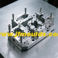
The injection mold is composed of several steel plates with various parts, which are basically divided:
A molding device (female die, male die), B positioning device (guide post, guide sleeve), c fixing device (I-plate, code die pit), d cooling system (water transport hole), e constant temperature system (heating pipe, heating wire), f flow channel system (nozzle hole, flow channel groove, flow channel hole), g ejection system (thimble, top stick)
In order to ensure the rationality and consistency of the mold production and processing technology, optimize the processing technology and improve the progress of mold production, each mold factory will generally formulate process standards suitable for the factory. This paper provides a reference standard.
1. The craftsman compiles the craft card
When compiling the process card, the craftsman shall indicate in detail the processing reservation, the orientation of the reservation, the roughness requirements and matters needing attention in the process card.
Processing process card preparation principle: in order to ensure the accuracy and quality of the premise, the priority is to use high processing efficiency equipment. The processing efficiency of milling machine, CNC and grinding machine is faster than that of wire cutting and electric pulse, especially the electric pulse processing efficiency is the slowest. The dimensions on the drawing cannot be changed at will (only technicians can change them).
2. Processing reserve principle
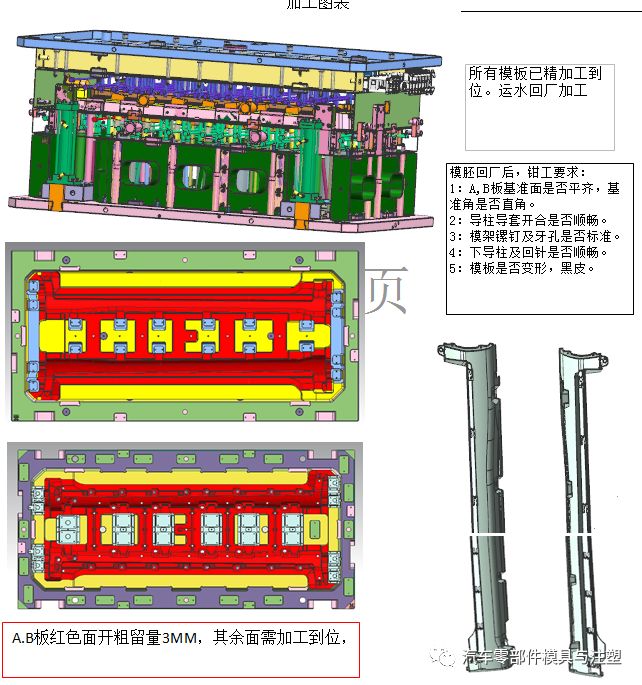
For workpieces requiring heat treatment, 0.25mm of grinder allowance is added on one side of the outline material preparation size before heat treatment, 0.2mm of unilateral allowance is reserved for parts requiring CNC rough machining of die kernels and inserts, 0.3-0.5mm of unilateral allowance is reserved for rough milling of the outline by fitter milling machine, 0.05mm of unilateral allowance is reserved for workpieces requiring grinder machining after wire cutting, and 0.1mm of grinding allowance is reserved for rough shape. CNC finishing, mirror polishing after electric pulse, leave a polishing allowance of 0.03mm on one side.
Automobile Model Design and Structure Course: It has been released on July 1
3. Machining accuracy requirements
The manufacturing accuracy of the mold size should be in the range of 0.005~0.02mm; The verticality is required to be in the range of 0.01~0.02mm; The coaxiality is required to be in the range of 0.01~0.03mm; The parallelism of the upper and lower planes of the moving and fixed die parting surfaces is required to be in the range of 0.01~0.03mm.
After the mold is closed, the gap between the parting surfaces is less than the overflow value of the molded plastic. The parallelism of the other template mating surfaces is required to be within the range of 0.01~0.02mm; The matching accuracy of the fixed part is generally within the range of 0.01~0.02mm. If there is no requirement for insertion of the small core or the influence on the size is not great, bilateral clearance fit of 0.01~0.02mm is preferable. The matching accuracy of sliding part is generally H7/e6, H7/f7 and H7/g6.
Note: If there is an insert with a hanging step on the mirror surface, the fit should not be too tight, otherwise the tool used for knocking will easily damage the mirror surface when the insert is knocked back from the front surface. If the product size is not affected, the clearance fit between the two sides is 0.01~0.02mm.
4. Principle of CNC electrode removal
The mold cavity core should first remove the appearance main electrode, then remove other main electrodes, and finally remove the local electrode; The overall processing of the fixed mold appearance electrode shall be considered. For the places where CNC angle is not cleared, wire cutting shall be used to clear the angle, so that the fixed mold appearance surface is complete and there are no joint marks. The reinforcing ribs, ribs and pillars with little difference in the depth of the moving mold can be processed together on one electrode as much as possible; the deeper ribs should be inserted, and the electrode side should be punched separately to prevent carbon deposition during electric pulse. The movable die electrode should not be cut by wire after CNC milling. If necessary, the electrode should be disassembled or cut by wire directly. The interval between the ribs and positions of the movable die or the pillars exceeds 35mm, which should be done separately to save copper.
The large electrode roughing spark position is 0.3mm on one side, and the finishing spark position is 0.15mm on one side; the general electrode roughing spark position is 0.2mm on one side, and the finishing spark position is 0.1mm on one side; the small electrode roughing spark position is 0.15mm on one side, and the finishing spark position is 0.07mm on one side.
5. CNC machining principles
If the appearance of the product allows, the mold cavity core that can be finished by CNC is preferred to be machined by CNC, and if the appearance of the product allows, the mold cavity core that cannot be finished in place is processed by CNC, and if the electrode cannot be processed in place, it is processed by electric pulse.
6. Dynamic and static mold kernel processing technology
1) Preparation of materials;
2) Milling machine processing: drilling water transport holes (the deepest part of the water transport hole plug is 3-4mm away from the horizontal water transport hole), threading holes, drilling and tapping screw holes, drilling and reaming pinholes, mold number, reference angle and hanging table giving way;
3)CNC machining: rough machining;
4) heat treatment processing: indicate the hardness requirements;
5) grinding machine processing: grinding six-sided square, the shape of which is aligned with the matching frame size (if the shape dimension of one mold kernel is mm-0.05mm than the drawing size by minus 0.03, if the shape dimension of the two mold kernels is two, the shape dimension of the two mold kernels combined direction is mm-0.05mm than the drawing size by minus 0.03) ⊥ 0.01, ∥ 0.01, the part that can be formed by grinding machine must be formed;
6) If CNC finishing is required for die kernels, CNC finishing shall be arranged. If there are fonts and die numbers in the cavity, lettering shall be required;
7) Wire cutting processing: medium wire processing insert hole, inclined top hole, top pin hole, nozzle hole, etc;
8) Electrical discharge machining: Single machining according to drawing and pulse indication;
9) Polishing: Write down the roughness and requirements of polishing on the process flow card, and mark the polishing area with a marker pen on the workpiece. If there is a mirror requirement, if the cycle is too late, rough polishing can be carried out before fine polishing;
10) Assembly;
11) Test the model.
7. Main body insert processing technology
1) Material preparation: The craftsman defines whether to process single piece or multiple pieces together according to the size and shape of the workpiece. If multiple pieces are processed together, the craftsman needs to map the processing ranking of the workpiece;
2) Milling machine processing: fitters process according to the workpiece drawing or the ranking drawing produced by the craftsman, drill the water transport hole (the deepest part of the water transport hole plug is 3-4mm away from the horizontal water transport hole), thread hole, drill and tap the screw hole, drill and ream the top needle hole, open the forming part roughly, number the mold, and give way to the hanging table;
3)CNC machining: if the workpiece needs CNC roughing, arrange CNC roughing;
4) heat treatment processing: indicate the hardness requirements;
5) Grinding machine processing: grinding six-sided square, the part that can be formed by the grinding machine must be ground and formed;
6) If CNC finishing is required for workpieces, CNC finishing shall be arranged. If the inserts have fonts and model numbers, lettering shall be required;
7) wire cutting processing: wire processing insert hole, inclined top hole, top pin hole, etc;
8) Electrical discharge machining: Single machining according to drawing and pulse indication;
9) Polishing: Write down the roughness and requirements of polishing on the process flow card, and mark the polishing area with a marker pen on the workpiece. If there is a mirror requirement, if the cycle is too late, rough polishing can be carried out before fine polishing;
10) Assembly;
11) Test the model.
8. Special-shaped insert processing technology:
Process 1:
1) Wire cutting processing: cutting the outer dimension of the middle wire cutting is accurate (A/B view), pulling tab, grinding machine with allowance for thickness, and thickening the forming part;
2) Grinding machine processing: grinding thickness, slope, forming;
3) electrical discharge machining;
4) polishing processing.
Process 2:
1) Wire cutting processing: medium wire cutting shape, insert hole, top pinhole, dimension cutting (view C), hanging table and forming place open thick;
2) Grinding machine processing: grinding height, hanging table, slope, forming;
3) electrical discharge machining;
4) polishing processing.
9. Simple insert processing technology
1) Wire cutting processing: fast wire cutting shape allowance grinder (A/B view), pull tab, thickness allowance grinder;
2) Grind the overall dimensions, grind the hanging table, slope, and shape;
3) electrical discharge machining;
4) polishing processing.
10. Round insert processing technology
1) Ceneless grinding: the overall dimensions of the grinding;
2) Grinder processing: angle cleaning at the hanging table;
3) Wire cutting: fast wire cutting length (0.1mm grinder allowance is left on one side), pinholes and exhaust holes are cut at the top;
4) grinding machine processing: grinding length, forming.
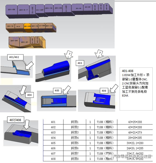
11. Inclined top processing technology
1) Wire cutting processing: medium wire cutting shape, head grinding with allowance to insert surface, grinding with allowance for other dimensions, grinding with allowance for pull tab thickness and grinding machine with I-shaped groove;
2) Grinding machine processing: grinding thickness, I-groove;
3) Assembly;
4) Pulse;
5) polishing;
6) Milling machine open oil groove.
12. Processing technology of inclined top seat
1) fitter preparation: 1.5mm for height, 0.5mm for width, and 5mm for length;
2) Milling machine processing: drilling and tapping screw holes;
3) heat treatment processing;
4) Grinding machine processing: grinding six-sided square, width size grinding;
5) wire cutting fast wire processing I-shaped groove, pull tab, thickness allowance grinding machine, height dimension is 1.2mm;
6) grinding machine processing: grinding machine dimensions, equipped with thimble plate, height dimension is 1mm.
13. Processing technology of inclined top guide block
1) Line cutting processing: fast wire cutting shape, leaving a reserved grinder;
2) Grinding machine processing: grinding six-sided square, the overall dimensions of the grinding;
3) milling machine processing: threading hole, screw hole;
4) Line cutting processing: fast wire cutting inclined top guide hole.
14. Processing technology of slide seat
1) Preparation of materials;
2) Grinding machine processing: grinding six-sided square, the overall dimensions of the grinding;
3) Milling machine processing: drilling through wire holes, drilling and tapping screw holes;
4) wire cutting processing: fast wire processing oblique guide pillar hole;
5)CNC finishing: Milling the size of the forming part.
15. Processing technology of briquette
1) Preparation of materials;
2) Milling machine processing: drill screw through holes, and open the forming part (unilateral reserved 0.3-0.5, grinder);
3) Grinding machine processing: grinding six-sided square, accurate grinding of external dimensions, forming.
16. Processing technology of locking block
1) Preparation of materials;
2) Grinding machine processing: grinding six-sided square, the overall dimensions of the grinding;
3) wire cutting processing; fast wire forming;
4) Milling machine processing: drilling and tapping screw holes.
17. Machining principle of ejector hole
Above Φ3 (including Φ3, Φ4, Φ5, Φ6) ejector hole processing adopts milling machine drilling and reaming; Below Φ3 or non-standard ejector hole, wire cutting processing, the bottom to avoid empty.
18. Wire hole processing principles
When all kinds of holes need to be processed by wire cutting, when the circumference of the inner wall is greater than Φ3 (including Φ3), the wire hole must be drilled.
19. The processing of the trademark and the need to throw the mirror mold
1) Allowance shall be left at the trademark after CNC finish milling of the mold kernel;
2) Wire cutting medium wire processing: trademark insert hole;
3) Electrical discharge machining: the depth of the hanging table is accurate;
4) Equipped with trademark core and installation fixture;
5) The residual pulse at the trademark shall be leveled; ⑥ Polishing.
20. Mold base processing technology
1) Milling machine processing: chamfering the inner frame, drilling screw holes, top pin holes, waterway holes, gate cup through holes, and inclined top hole through holes;
2)CNC machining: milling pouring cup counterbore, inclined top seat hole, guide block hole, row groove, hot runner mold plate A needs CNC machining, mold foot engraving processing.
21. Post-mold processing technology of mounting frame with grid-like reinforcing ribs
This kind of mounting frame after the processing of mold rib position according to different mold categories, choose different processing technology.
1) We directly use the whole electrode for a type of mold to ensure the unity of the product;
2) When the processing technology of a non-type mold is selected, it can be allocated according to the actual processing amount. The electrode can be divided or integrated. If the rib position is through groove, the wire can be cut thick first, and then the grinder can be refined.
22. Need wire cutting fixture or electrode, batch pulse workpiece
For some workpieces (such as the core of multi-function two-plug socket), wire cutting fixture or electrode is required. The processing flow of batch pulse workpieces is as follows:
1)CNC out of the ranking chart;
2) wire cutting drawing according to the size of the processing fixture or electrode;
3) After the wire cutting process is completed, if the electrode needs to be CNC processed, the electrode will be handed over to the CNC and the fixture will be handed over to the fitter;
4)CNC machining electrode, and discharge diagram;
5) Pulse machining;
6) Polishing.
23. Calculation of support column height
The height of the support column below the 3030 of the formwork is 0.08-0.1mm higher than the formwork foot, 0.1mm higher than the 3030, 0.1-0.12mm higher than the 3535, and 0.12-0.15mm higher than the 3535.
24. The thimble processing technology
φ 2 and above thimble cutting machine cutting length allowance grinding machine, grinding machine processing length size grinding (fitter own processing); The thimble wire cutting processing size below φ 2 is accurate. The flat thimble and barrel shall be made by wire cutting length allowance grinding machine; the grinding machine shall be used for processing, and the length and dimension shall be ground accurately.
1. EDM
(1) Basic principle
EDM is a special processing method that uses the electric erosion generated by the pulse discharge between the two poles immersed in the working fluid to remove conductive materials, also known as discharge machining or electric erosion machining, English for Electrical Discharge Machining, referred to as EDM.
(2) Basic equipment: EDM machine tools.
(3) Main features
Can process materials and workpieces with complex shapes that are difficult to cut by ordinary cutting methods; No cutting force during processing; No burrs, tool marks, grooves and other defects are produced; The tool electrode material does not need to be harder than the workpiece material. Direct use of electric energy for processing is convenient for automation. After processing, metamorphic layer is generated on the surface, which must be further removed in some applications. Purification of working fluid and treatment of smoke pollution generated in processing are more troublesome.
(4) Scope of use
Processing molds and parts with complex shapes of holes and cavities; Processing various hard and brittle materials such as hard alloy and hardened steel; Processing deep fine holes, special-shaped holes, deep grooves, narrow slits and cutting sheets, etc. Processing various forming tools, templates, thread ring gauges and other tools and measuring tools.
2. WEDM
(1) Basic principle
The use of continuously moving thin metal wire (called electrode wire) as the electrode, the workpiece pulse spark discharge erosion to remove metal, cutting and forming. English for wire cut Electrical Discharge Machining, referred to as WEDM, also known as wire cutting.
(2) Basic equipment: WEDM machine tool.
(3) Main features
WEDM, in addition to the basic characteristics of EDM, there are some other characteristics:
① It is not necessary to manufacture tool electrodes with complex shapes to process any two-dimensional surface with a straight line as the generatrix;
② Can cut narrow slits of about 0.05mm;
In the process, all the excess materials are not processed into waste chips, which improves the utilization rate of energy and materials;
④ In the low-speed wire EDM process where the electrode wire is not recycled, the electrode wire is continuously updated, which is beneficial to improve the machining accuracy and reduce the surface roughness;
⑤ The cutting efficiency achieved by WEDM is generally 20-60mm 2/min, up to 300mm 2/min; the machining accuracy is generally ± 0.01 to ± 0.02mm, up to ± 0.004mm; the surface roughness is generally Ra2.5 to 1.25 microns, up to Ra0.63 microns; the cutting thickness is generally 40-60mm, and the maximum thickness can reach 600mm.
(4) Scope of use
Mainly used for processing: a variety of complex shapes and precision small workpieces, such as punching die punch, die, punch, fixed plate, discharge plate, etc.; forming tool, template, EDM forming metal electrode; a variety of micro-holes, narrow slits, arbitrary curves. It has the outstanding advantages of small machining allowance, high machining precision, short production cycle and low manufacturing cost, and has been widely used in production. At present, WEDM machine tools at home and abroad have accounted for more than 60% of the total number of EDM machine tools.
3. Electrolytic machining (Electro Chemical Machining)
(1) Basic principle
Based on the principle of anodic dissolution in the electrolytic process and with the help of a formed cathode, the workpiece is processed into a certain shape and size, called electrolytic processing.
(2) Scope of use
Electrochemical machining has significant advantages for the machining of difficult-to-machine materials, complex shapes or thin-walled parts. Electrolytic machining has been widely used, such as barrel rifling, blades, integral impeller, mold, special-shaped holes and special-shaped parts, chamfering and deburring. And in the processing of many parts, the electrolytic machining process has occupied an important and even irreplaceable position.
(3) Advantages
Wide range of processing. Electrolytic machining can process almost all conductive materials, and is not limited by the mechanical and physical properties such as strength, hardness and toughness of the material, and the metallographic structure of the material after processing basically does not change. It is often used in the processing of hard alloy, high temperature alloy, hardened steel, stainless steel and other difficult to process materials.
(4) Limitations
Machining accuracy and processing stability is not high, processing costs are higher, and the smaller the batch, the higher the additional cost of a single piece.
4. Laser processing
(1) Basic principle
Laser processing, is the use of light energy through the lens focus on the focus to achieve a high energy density, in a very small time to melt or vaporize the material and be etched down, to achieve processing.
(2) Main features
Laser processing technology has the advantages of less material waste, obvious cost effect in large-scale production, and strong adaptability to processing objects. In Europe, the welding of special materials such as high-end car shells and bases, aircraft wings and spacecraft fuselages is basically laser technology.
(3) Scope of use
Laser processing is the most commonly used application of laser system. The main technologies include: laser welding, laser cutting, surface modification, laser marking, laser drilling, micro-machining and photochemical deposition, stereolithography, laser etching and so on.
5. Electron beam machining
(1) Basic principle
Electron beam machining is the machining of materials using the thermal or ionizing effects of high-energy converging electron beams.
(2) Main features
High energy density, strong penetrating ability, wide range of primary penetration, large weld width ratio, fast welding speed, small heat-affected zone, and small working deformation.
(3) Scope of use
Electron beam processing of a wide range of materials, the processing area can be extremely small; processing accuracy can reach the nanometer level, to achieve molecular or atomic processing; high productivity; processing of small pollution, but high cost of processing equipment; can be processed micropores, narrow seams, etc., but also can be used for welding and fine lithography. Vacuum electron beam welding technology is the main application of electron beam processing in automobile manufacturing industry.
6. Ion Beam Machining
(1) Basic principle
Ion beam processing is in a vacuum state, the ion stream generated by the ion source is accelerated and focused to the surface of the workpiece to achieve processing.
(2) Main features
Since the ion current density and ion energy can be precisely controlled, the processing effect can be precisely controlled, and ultra-precision processing at the nanoscale and even at the molecular and atomic levels can be realized. During ion beam processing, the pollution generated is small, the processing stress and deformation are extremely small, and the adaptability to the processed material is strong, but the processing cost is high.
(3) Scope of use
Ion beam processing can be divided into etching and coating according to its purpose.
1) Etching processing
Ion etching is used to process the grooves on the air bearing of the gyroscope and the dynamic pressure motor, with high resolution, good precision and repeatability. Another aspect of ion beam etching applications is the etching of high precision graphics, such as electronic components such as integrated circuits, optoelectronic devices, and optical integrated devices. Ion beam etching is also used to thin materials and make penetrating electron microscope test pieces.
2) Ion beam coating processing
Ion beam coating processing has two forms: sputtering deposition and ion plating. Ion plating can be a wide range of materials, regardless of metal, non-metal surface can be plated metal or non-metal film, a variety of alloys, compounds, or some synthetic materials, semiconductor materials, high melting point materials can also be plated.
Ion beam coating technology can be used for coating lubricating film, heat-resistant film, wear-resistant film, decorative film and electrical film.
7. Plasma arc processing
(1) Basic principle
Plasma arc processing is a special processing method that uses the heat energy of plasma arc to cut, weld and spray metal or non-metal.
(2) Main features
1) Micro-plasma arc welding can weld foil and sheet;
2) with a small hole effect, can better achieve single-sided welding double-sided free forming;
3) Plasma arc energy density, high arc column temperature, strong penetration ability, 10-12mm thickness steel can not open groove, can be a penetration double-sided forming, welding speed, high productivity, small stress deformation;
4) the equipment is more complex, the gas consumption is large, only suitable for indoor welding.
(3) Scope of use
Widely used in industrial production, especially in aerospace and other military and cutting-edge industrial technology used in the welding of copper and copper alloys, titanium and titanium alloys, alloy steel, stainless steel, molybdenum and other metals, such as titanium alloy missile shells, aircraft on some thin-walled containers.
8. Ultrasonic machining
(1) Basic principle
Ultrasonic machining is the use of ultrasonic frequency for small amplitude vibration of the tool, and through it and the workpiece free in the liquid between the abrasive on the surface to be processed by the hammering effect, so that the workpiece material surface gradually broken special processing, English referred to as USM. Ultrasonic machining is often used for perforation, cutting, welding, nesting and polishing.
(2) Main features
It can process any material, especially suitable for the processing of various hard and brittle non-conductive materials. The processing precision of the workpiece is high, the surface quality is good, but the productivity is low.
(3) Scope of use
Ultrasonic machining is mainly used for various hard and brittle materials, such as glass, quartz, ceramics, silicon, germanium, ferrite, precious stones and jade, etc. (including round holes, special-shaped holes and curved holes, etc.), cutting, Grooving, nesting, engraving, deburring of batch small parts, polishing of mold surface and grinding wheel dressing, etc.
9. Chemical processing
(1) Basic principle
Chemical processing (Chemical Etching), is the use of acid, alkali or salt solution on the workpiece material corrosion dissolution, in order to obtain the desired shape, size or surface state of the workpiece special processing.
(2) Main features
1) can process any cutting metal materials, not limited by hardness, strength and other properties;
2) Suitable for large-area processing, and can process multiple pieces at the same time;
3) No stress, crack, burr, surface roughness of Ra1.25-2.5 μm;
4) Easy operation;
5) Not suitable for processing narrow slots and holes;
6) It is not advisable to eliminate defects such as uneven surface and scratches.
(3) Scope of use
Suitable for large area thickness reduction processing; suitable for processing complex holes on thin-walled parts.
Related News
Special mold design
2025-07-24
Special mold design1 Stacked moldThe stacked mold simultaneously produces inject...
Classification of injection molds
2025-09-06
Classification of injection moldsDifferent types of molds have different require...
Multiple mold designs
2025-07-25
Multiple mold designsIn-mold labeling processThin-walled plastic packaging produ...
Methods for the easy breakage of the internal position of the mold and the easy damage of the screw column during the mold opening process
2025-08-07
Methods for the easy breakage of the internal position of the mold and the easy ...
Check the thickness of the wall
2025-09-17
Check the thickness of the wallThe principles for designing the wall thickness o...
Injection mold commonly used six kinds of mold materials
2025-06-19
The choice of steel not only affects the service life of the mold, but also affe...