Types and basic requirements of mold design drawings
Types and basic requirements of mold design drawings
To shorten the production cycle of molds, designers need to provide drawings that meet various requirements in the shortest possible time, including: simple mold structure drawings, plastic part drawings, cavity layout drawings, mold base drawings, sketches of moving and fixed mold parts, mold assembly drawings, part drawings, wire cutting drawings, push rod layout drawings, electrode drawings, and 3D model drawings
(1) Simple diagram of the mold structure
The simple diagram of the mold structure is mainly used for ordering mold bases, moving and fixed mold inserts, and opening frames, etc. The structural schematic diagram usually only includes the dynamic mold schematic diagram and one main sectional view. It should indicate the mold base specifications, opening frame dimensions, dynamic and fixed mold dimensions, the position of the plastic part in the mold, the plastic part parting situation and the feeding position. The steps for drawing the structural schematic diagram are as follows:
The gating system of the mold is determined based on the shape, size and quantity of the plastic part, which directly decides whether the mold base is a two-plate mold base or a three-plate mold base.
2. Determine the position of the parting surface based on the shape of the plastic part. The planar parting surface is preferred, followed by the inclined parting surface, and the arc-shaped parting surface is the last choice. If the parting line affects the appearance, the customer's opinion should be sought. After the parting surface is determined, it is necessary to consider whether the plastic part will stick to the mold when the mold is opened with such a parting.
3. Decide which positions to use inserts. Weak structures, structures that are difficult to polish and machine, exhaust difficulties, and often require inlaying.
4. Decide how the plastic part is demolded. Whether the plastic part requires special demolding structures such as lateral core-pulling, forced demolding, secondary or even multiple demolding, pneumatic demolding, push block demolding or push plate demolding. If only push rods and push tubes are used for demolding, the position, size and quantity of the push rods must be taken into
consideration. The demolding method of the plastic part has a significant impact on the mold structure. When designing the push rod, the layout of the cooling water must be considered simultaneously and should not interfere with each other.

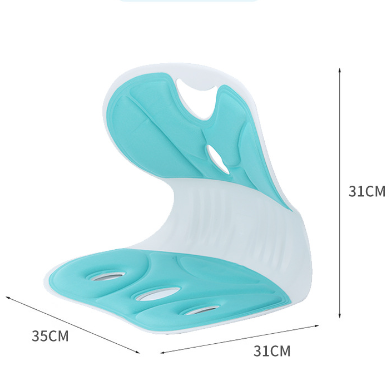
Lumbar support seat mold Manufacturer in China (jfmoulds.com)
5. Determine the location of the cooling water channels. The cooling water channels should be placed at the bottom or beside the cavity as much as possible, passing through the areas with the most heat. If direct cooling water cannot be passed through, heat dissipation needles or crinkled copper inserts can be considered.
6. Determine the size and steel of the mold inserts. After comprehensively considering the above factors, the size of the mold insert can be determined. The size of the insert should be an integer, and the thickness should be taken as the standard. The type of steel used depends on the type of plastic, whether the plastic part is transparent, the precision of the plastic part and the size of the batch.
7. Determine the size and specification model of the mold base. The size and specification model of the mold base should be determined based on the feeding method, the size of the inner mold inserts, and whether hot runners, double push plates, and lateral core-pulling mechanisms are adopted.
(2) Plastic part drawing
After having a clear understanding of the customer's requirements and the performance of the plastic parts, and fully considering the draft Angle, tolerance fit, etc., the customer's plastic part drawings are corrected and input into the computer, and then archived according to the company's standard numbers.
(3) Cavity alignment diagram
For some more complex molds that are difficult to draw by hand, designers can draw them on the computer according to the instructions of the supervisor. The function is the same as that of the mold structure diagram. The cavity alignment diagram does not need to draw push rods, struts, springs, etc. It only needs to draw the alignment of the moving and fixed molds and a side view. When there is a side core-pulling mechanism, the side core-pulling structure should be drawn completely. The seating arrangement, pillow position, and material intake should also be expressed. If there is already a plastic part drawing, it can be adjusted to the position in the mold. If not, you can just draw a general outline and its important parts.
(4) Mold frame drawing
For non-supplier standards or formwork frames that need to be processed by opening frames in the formwork frame factory, formwork frame drawings should be drawn. The mold frame drawing needs to be faxed to the supplier for production, so the dimensions and requirements to be processed should be clearly expressed on A4 paper. The dimensions of the standard mold frame part can be omitted and not marked. The content of the formwork frame drawing: formwork (fixed formwork, moving formwork, square iron, push rod fixed plate, push rod bottom plate, moving and fixed formwork fixed plate); Guide pins and guide sleeves, screws below the guide pins; Connecting screws and locating pins between templates; Push rod plate guide posts and guide sleeves; Reset rod (no need to draw the number); Push rod plate limit nail or limit pull rod; Push rod plate screw Prying mold pits (four corners between each board, including between the needle boards); The exhaust groove under the guide column; Hanging die screw holes, stacking die slots; Inserts, sliders, mold clamping blocks, square positioning blocks, face positioning blocks, etc. Dimensions (including planar coordinate dimensions, plate thickness, part size and quantity, precision frame dimensional tolerance, mold lifting position, mold prying slot dimensions); The names of the steel materials for each template.
(5) Sketches of moving and fixed mold parts
To shorten the mold-making cycle, for general molds, when the assembly drawing is not completed, the mold part development drawing can be issued first to ensure the smooth progress of the workshop's material preparation, grinding of the reference surface, drilling of screw holes, frame matching and other work. Only the main dimensions need to be marked on the sketch
(6) Mold assembly drawing
The mold assembly drawing is one of the main drawing forms in the mold design department. The mold assembly drawing should be able to express the structure of the mold, the assembly relationship between parts, the working principle of the mold, as well as the technical requirements and inspection requirements for manufacturing the mold. The assembly drawing must be drawn 1:1. Before drawing the mold assembly drawing, carefully study the customer's plastic part drawings and other technical requirements, and clarify the mold parting table. If similar molds have been made before, you can refer to their documents.
Before drawing the mold assembly drawing, there must be a completely accurate plastic part drawing. Sometimes, the plastic part drawing needs to be appropriately corrected, such as adding necessary draft angles. If there are tolerance requirements, the tolerances should be converted. Generally, it is necessary to consider correcting to a shape that is conducive to adding glue in the future. When converting the plastic part drawing into the cavity drawing inside the mold base, first multiply by the shrinkage rate plus 1, then perform mirror processing (reflection). At the same time, pay attention to not placing the dynamic and fixed mold cavity drawings in the wrong position. When arranging, ensure that the reference of the cavity drawing is an integer relative to the reference of the mold base.
Auto Mould_Taizhou Jiefeng Mould Co.,Ltd. (jfmoulds.com)
The multi-cavity mold drawing should indicate the cavity number. For multi-cavity point gate molds such as gears, the corresponding cavity number should also be marked on the runner, such as CAV.No.1, CAV.No.2, etc. The fine structures in the mold assembly drawing should be enlarged. The layout plan of the inclined push rod (including the bottom slide seat) should be expressed clearly, and the dimensions should be marked clearly to facilitate processing. To prevent interference with other parts, the serial numbers of each hole should be noted on the mold assembly drawing. For example, the support columns should be marked with SP and the serial numbers should be written. A complete mold assembly drawing should include the following contents.
Sufficient graphics that can express the structure of the mold
2. Complete and accurate dimensions
3. List of push rods (clearly marked for flat top push rods, support push rods and push tubes, and it is best if it can be generated automatically).
4. Part number, title bar, detail bar, and modification bar.
5. Schematic diagram of the cooling water line axis measurement. In special cases, an exhaust schematic diagram is also required.
6. Various hole positions and their codes.
Related News
NowOn behalf of the manufacturing industry precision "molding magician"
2025-06-29
NowOn behalf of the manufacturing industry precision "molding magician" In today...
Common defects of Injection molded products and their solutions
2025-07-29
Common defects of Injection molded products and their solutions The diagnosis...
The positioning ring and screws of the mold
2025-10-07
The positioning ring and screws of the moldOne: Positioning circleThere are two ...
The limit switch of the mold
2025-10-08
The limit switch of the mold In some cases, the actions of different mechan...
Dimension marking of the mold design drawing
2025-09-10
Dimension marking of the mold design drawingI. General Requirements for Dimensio...
Define a new paradigm for the injection mold industry through technological breakthroughs and ecological reconstruction
2025-07-04
Define a new paradigm for the injection mold industry through technological brea...


