Mold exhaust (2)
Mold exhaust (2)
One: Insert exhaust
In the thin-walled structure cavity, the end of the melt flow, the bottom of the blind holes in the mold cavity, the end of the solid column position of the plastic part, the bottom of the plastic part's reinforcing ribs and screw columns, and the corners of the complex cavity are all the places where air is most likely to be trapped. The exhaust in these places mainly relies on the depth of the exhaust groove on the contact surface between the inserts, which is selected according to the plastic product, with a length of 2.00 to 4.00mm. The depth B of the secondary exhaust groove is taken as 0.50mm, and the depth of the tertiary exhaust groove is taken as 1.00mm.
When using inserts for exhaust, the following two points must be noted.
The three-stage exhaust slots must extend outside the mold and be connected to the atmosphere.
2. The exhaust slots between the inserts are prone to being clogged with glue powder or dirt and must be cleaned regularly.
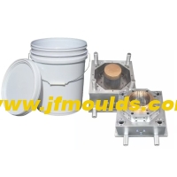
Plastic bowl mold Manufacturer in China (jfmoulds.com)

Two: Exhaust through push rods and push tubes
The fit tolerance between the push rod and the push tube and the insert is H7/f7, which is an intermediate fit. During the injection molding process, this can be used for venting. If the volume of the plastic part is large and the cavity is severely trapped with air, venting grooves can also be machined on the push rod and push tube.
A represents the depth of the first-level exhaust groove, which is determined based on the type of plastic. However, since it is the maximum size on the cylindrical surface, it can be increased by 0.01 to 0.02mm on the basis. The length C of the first-stage exhaust groove is taken as 3 to 5mm.
The length D of the secondary exhaust groove can be taken as 5 to 8mm.
B represents the depth of the secondary exhaust groove, which can be taken as 0.4 to 0.5mm, and the length D of the secondary exhaust groove can be taken as 5 to 8mm.
The mating length L of the push rod and push tube with the insert is approximately three times the diameter of the push rod, but it should not be less than 10mm and should not exceed 20mm. On the non-mating length, there should be a 0.5mm clearance on one side.
Three: Add inserts at the trapped air points to release the air
1. Strengthen the ribs for exhaust
The area around the reinforcing ribs is the place where air is most likely to accumulate. Generally speaking, when the height X of the reinforcing ribs is less than 5mm, there is no need to install insert exhaust. When the height X of the reinforcing ribs is greater than 8mm, it is necessary to use inserts for venting. When the height of the reinforcing ribs X=5 to 8mm, it should be determined based on specific circumstances. At this point, the exhaust groove is located on the contact surface of the insert and is the same as the insert exhaust.

2. Exhaust air at areas with thin walls but large areas of plastic parts
If the plastic part has a thin wall but a large area, it is often difficult to fill the melt due to trapped air. At this time, inserts must be added to vent the air. Two different ways of spelling. The exhaust groove is located on the exhaust of the reinforcing ribs at the contact surface of the insert, which is the same as the insert exhaust in Section 5.6.
3. Exhaust for deep cylindrical plastic parts
For box-shaped, cylindrical and shell-shaped plastic parts with large height dimensions, if the material is fed from the bottom through the side gate, air is very likely to be trapped at the top. Countermeasures must be considered at the very beginning of the mold design. This is a common method for assembling this type of plastic parts. However, since the surface of the plastic parts may leave creases, it is necessary to inform the customer in advance and obtain their consent before assembling. If the customer does not agree with such inlaying due to high appearance requirements, the exhaust method can be considered, but this will affect the cooling of the moving mold inserts and the arrangement of the push rods.

Commodity Mould_Taizhou Jiefeng Mould Co.,Ltd. (jfmoulds.com)
4. Add glue (material) at the trapped air area
Slightly altering the structure of the plastic part at the trapped air in the cavity can also improve the flow of the melt and avoid the influence of trapped air on the molding quality of the plastic part. The following are two typical examples.
(1) Closed reinforcing ribs
For the assembly of large closed height dimensions of reinforcing ribs (commonly known as speaker ribs) such as small speakers, in order to reduce the influence of trapped air on the flow of the melt, enhance the strength and rigidity of the reinforcing ribs, and reduce the deformation of the reinforcing ribs after demolding, a semi-cylindrical structure can be uniformly added around the periphery of the reinforcing ribs. The height of the semi-cylindrical structure above the reinforcing ribs is approximately 0.50mm.
(2) Add a slag collection bag at the trapped gas area
At the junction of two or more melt streams, it is often the place where trapped gas occurs. Adding a slag collection bag at the trapped gas point is one of the methods to solve the influence of trapped gas on the molding quality of plastic parts.

Related News
The selection of mold base specifications and models
2025-09-28
The selection of mold base specifications and models(1) Selection of two-plate m...
Exploring Injection Molds: Unlocking the Core Code of Plastic Molding
2025-07-10
Exploring Injection Molds: Unlocking the Core Code of Plastic Molding In the ...
How to solve the problems of whitening, charring and deformation of the bone position at the water outlet of the mold
2025-08-16
How to solve the problems of whitening, charring and deformation of the bone pos...
Calculation of injection mold forming dimensions
2025-10-10
Calculation of injection mold forming dimensionsI. Calculation Method for Genera...
The innovative design and intelligent development trend of injection molds
2025-07-09
The innovative design and intelligent development trend of injection molds In...
Determination of mold base size
2025-09-29
Determination of mold base size1: Determine the length, width and height of the ...