Limit pins and springs of the mold
Limit pins and springs of the mold
One: Limit pin
The function of the limit nail is to create a certain gap between the push rod plate and the bottom plate of the moving mold, preventing deformation of the template or the connection between the rod plate and the moving mold
Garbage fell between the mold bottom plates, causing the push rod plates to fail to reset accurately. Limit nails, commonly known as garbage nails, are typically made of P-20 material.
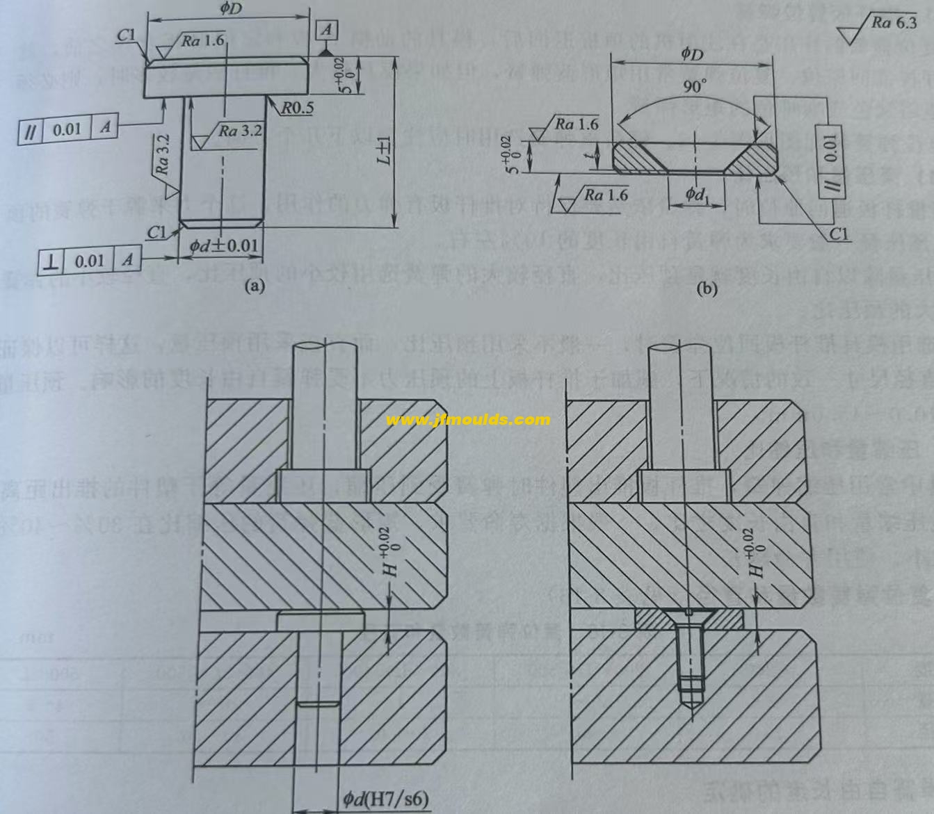
(1) Specification and model of limit pin
There are two standard shapes of limit pins.
Automobile lamp mold Manufacturer in China (jfmoulds.com)

(2) The size of the limit pin
(3) Assembly of limit nails
The limit pins should be installed on the base plate of the moving mold. For integral limit pins, interference fit should be adopted.
② The position of the limit pin. Limit nails should be added under all reset rods, at the dense areas of push rods and under the inclined push rods to withstand the expansion force during mold injection.
Two: Spring
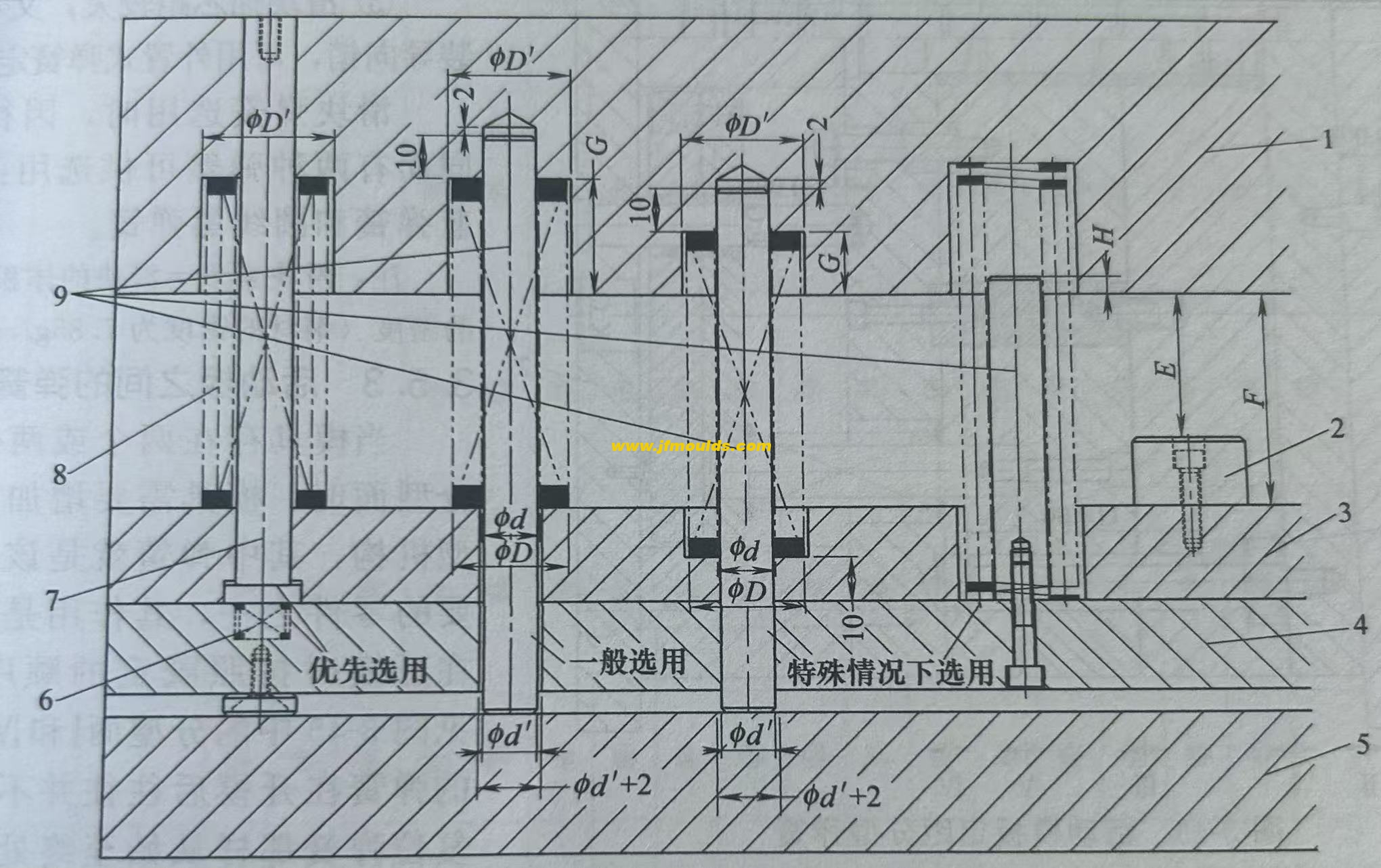
In the mold, springs are mainly used as auxiliary power for moving components such as the reset of the push rod plate, the positioning of the slider in the lateral core-pulling mechanism, and the spacing and parting of the movable template. Since springs lack rigid thrust and are prone to fatigue failure, they are not allowed to be used alone
Use. The springs in the mold include rectangular blue springs and circular black springs. Because rectangular blue springs have a greater elastic coefficient, stronger rigidity and a larger compression ratio than circular black springs, rectangular blue springs are commonly used in molds.
(1) Push rod plate reset spring
Push the push rod plate back to its original position. The reset spring commonly used is a rectangular blue spring, but if the mold is large and there are many push rods, it must be
Consider using green or coffee-colored rectangular springs. When choosing a light-load thumbnail, the following aspects should be noted.
1. Preloading amount and preloading ratio
When the push rod plate returns to its original position, the spring still needs to maintain an elastic force on the push rod plate. This force comes from the top pressure of the spring, and the pre-pressure is generally required to be about 10% of the free length of the spring.
The preload amount divided by the free length gives the preload ratio. For springs with a larger diameter, a smaller preload ratio should be selected.
When selecting the return spring for the mold push rod plate, the preload ratio is generally not used, but the preload amount is directly adopted. This can ensure that, under the condition of consistent spring diameter dimensions, the preload applied to the push rod plate is not affected by the free length of the spring. The preload is generally taken as 10.0 to 15.0mm.
2. Compression amount and compression ratio
Compression springs are commonly used in molds. When the push rod plate pushes out the plastic part, the spring is compressed, and the compression amount is equal to the distance the plastic part is pushed out. The compression ratio is the ratio of the compression amount to the free length. Generally, according to the service life requirements, the compression ratio of rectangular blue springs is between 30% and 40%. The smaller the compression ratio, the longer the service life.
3. Number and diameter of reset springs
4. Determination of the free length of the spring
① Free length calculation: The free length of the spring should be determined based on the compression ratio and the required compression amount. In the formula L free =(E P)/S
E is the stroke of the push rod plate, E= the minimum distance the plastic part is pushed out 15 to 20mm.
P represents the preload amount, which is generally taken as 10 to 15mm. It is determined based on the resistance during reset. The smaller the resistance, the smaller the preload. Usually, it can also be selected according to the size of the mold frame. For mold frames 3030(inclusive) or less, the preload amount is 5mm; for mold frames 3030 or more, the compression amount is 10 to 15mm.
S represents the compression ratio, typically taken as 30% to 40%. The free length should be determined based on factors such as mold life, mold size, and the distance between plastic parts. The standard length should be taken upwards.
If the calculated length is greater than the minimum length Lmin, the calculated length shall prevail.
The free length must be in accordance with the standard length and must not be cut for use. It is preferred to use multiples of 10
5. Assembly of the reset spring
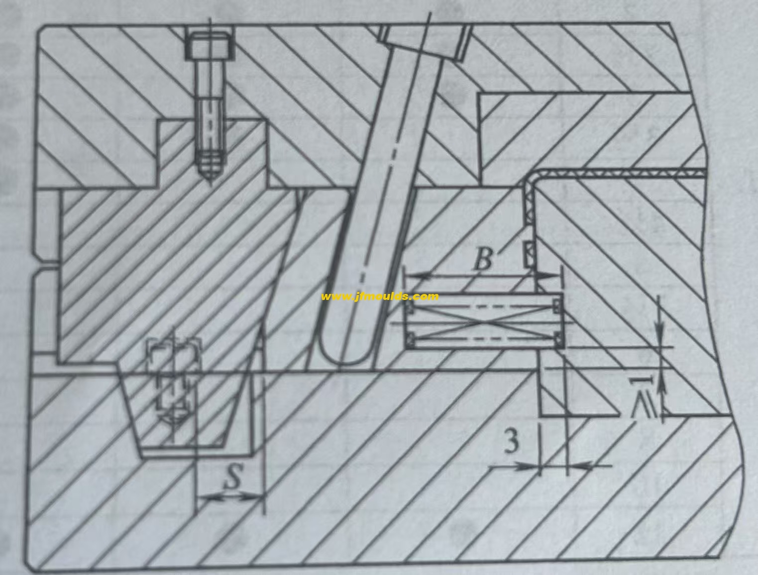
(2) Design of the slider positioning spring in the lateral core-pulling
The spring in the lateral core-pulling mechanism mainly serves a positioning function. After the mold is opened, when the inclined guide column and the wedge block leave the slider, the spring holds against the slider and does not slide back. The commonly used diameters of springs are 10mm, 20mm and 25mm. The pressure ratio can be 12mm or 16mm, and the compression ratio can be 1/4 to 1/3. The quantity is usually two.
Calculation of the free length of the slider spring: L free two-slider stroke S×3, where S is the core-pulling distance of the slider. Freedom is the free length of the spring, and the standard length should be taken upwards.
B = Free length - preload - core-pulling distance
The preload amount can be determined through calculation: slider preload amount - pressure/elastic coefficient. The upward core-pulling pressure is the slider plus the weight of the side core-pulling. When pulling the core-pulling downward or left and right, the preload can be taken as 10% of the free length.
The preloading amount can also be based on the following empirical data
Under normal circumstances, the preload after bouncing is 5mm.
If the slider is for upward core-pulling and its mass exceeds 8 to 20kg, the preload should be increased to 10mm. Meanwhile, the total length of the spring is multiplied by the stroke of the slider, S×3.5, and then rounded up to the nearest whole number.
If the slider is for upward core-pulling and its mass exceeds 20kg, the preload should be increased to 15mm.
The spring in the slider should be prevented from popping out. Therefore, the spring assembly hole should not be too large.
When the core-pulling distance of the slider is relatively large, a guide pin should be installed.
The core-pulling distance of the slider is relatively large and it is not convenient to install guide pins. An external spring can be used for positioning. When choosing a slider spring, there are two types of springs available for selection based on different strokes: rectangular blue springs and circular black springs.
Note: The weight of the slider × the volume of the slider × the steel material
The density (the density of steel is 7.85g/cm ³)
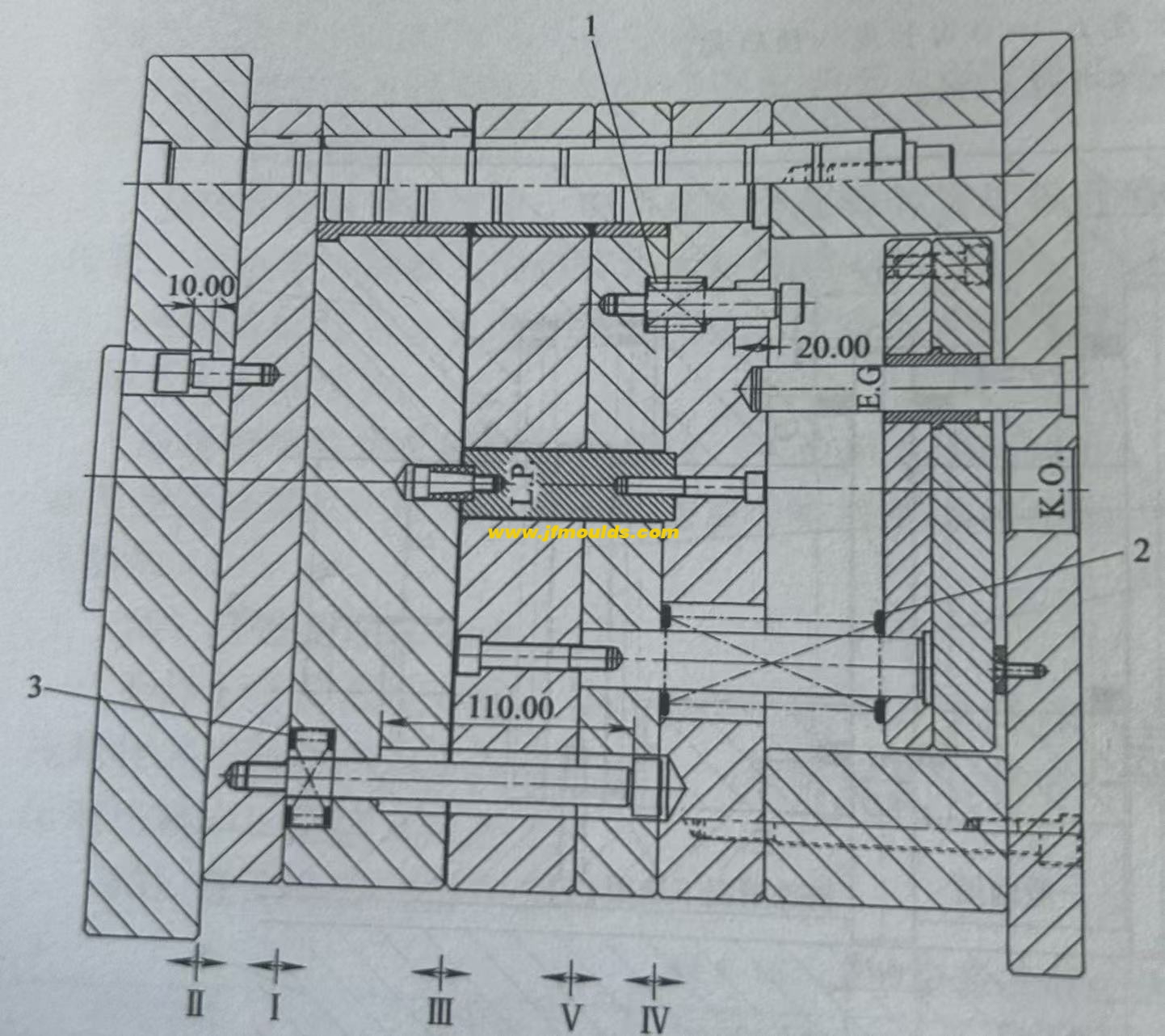
(3) Springs between the movable plates
When a mold has two or more parting surfaces, a space-fixing parting mechanism needs to be added to the mold. Among them, the spring is one of the important parts of this mechanism. Its function is to enable the mold to open in the predetermined sequence during mold opening, with parting surfaces I and V. Here, the spring usually does not need to be in a compressed state from beginning to end like the reset spring after mold opening. The spring only needs to be pressed on this parting surface
For the first 10 to 20mm of opening, just maintain the thrust on the template. As long as this surface is opened on time, its task is completed. For the three-plate mold that usually adopts the point gate gating system, the springs used on the first parting surface are all rectangular yellow springs of $40mmX30mm. The opening springs for other molds can be selected according to specific circumstances.
Related News
Entering the World of Injection Molds: An Analysis of Technology and Industrial Development from Multiple Perspectives
2025-06-28
Garbage can mold Manufacturer in China (jfmoulds.com)intotheWorldofInjectionMold...
Solutions to the problems of column bending deformation, delamination, surface peeling and frequent pressing of small spouts in the mold
2025-08-18
Solutions to the problems of column bending deformation, delamination, surface p...
Panoramic Insight into the Injection Mold Industry: Forging Ahead in the Wave of Change
2025-07-04
Panoramic Insight into the Injection Mold Industry: Forging Ahead in the Wave of...
The trapped air adjustment of the mold is difficult, and the deformation and the bottom row position pulling mold treatment method of the face shell
2025-08-12
The trapped air adjustment of the mold is difficult, and the deformation and the...
The selection of mold base specifications and models
2025-09-28
The selection of mold base specifications and models(1) Selection of two-plate m...
Solutions to wire clamping, surface indentation and punch marks in molds
2025-08-14
Solutions to wire clamping, surface indentation and punch marks in moldsThe clam...
