Lock module and support column
Lock module and support column
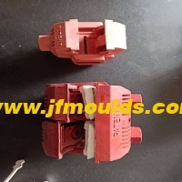
One: Lock module
The function of the lock module is to prevent the mold from opening from the parting surface during transportation or handling, which could cause mold damage or personal safety accidents. The lock module cannot merely lock the moving and fixed templates; all templates that may be opened must be locked.
1. Installation method of the lock module
The lock module must be installed on the front of the injection molding machine operator.
An additional screw hole should be machined on either the fixed mold A plate or the moving mold B plate. The position should be based on the principle of not hindering production. Its function is to fix and lock the template during mold production without the need for removal.
chair injection mold Manufacturer in China (jfmoulds.com)

2. Form of the lock module
There are two forms of standard lock modules. For the commonly used waist-shaped hole lock modules, unless requested by the customer, hook-shaped lock modules are generally not adopted.
3. Lock module size
The size of the lock module depends on the size of the mold. Among them, A and B depend on the quantity and thickness of the templates to be locked, E is taken as 10-15mm, and d is equal to the diameter of the screw plus 1mm.

4. Assembly of the lock module
Generally speaking, a mold must be equipped with two lock modules, located on both sides of the mold and symmetrically arranged.
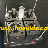
Two: Support columns
The support column, also known as the support column, is mainly used to withstand the expansion force exerted by the melt on the moving template during the injection molding process of the mold, preventing the moving template from deforming under the action of the expansion force and thereby enhancing the rigidity of the mold. The shape of the support column is cylindrical and the material is 45 steel or yellow grade steel S50C.

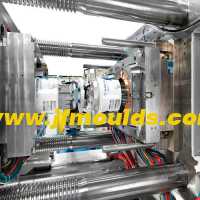
1. Assembly of support columns
The support columns are fastened to the base plate of the moving mold by screws.
Assembly precautions
1. The position of the support columns should be as close as possible to the middle of the mold. If space permits, the diameter should be as large as possible.
2. Unmarked chamfer C = 1.
3. Take 1.5 to 2.0mm on one side of the gland between the support column and the push rod plate, that is, D=d (3 to 4mm).
4. The support columns must be as high as iron. The relationship is as follows:
When the width dimension of the mold is less than 300mm: H1 0.05mm;
When the width of the mold is less than 400mm :H1 0.1mm;
When the width of the mold is between 400 and 700mm :H1 0.15mm;
When the width of the mold is greater than 700mm :H1=H 0.2mm
The distance between the support columns and the square irons should be no less than 25mm.
The distance between the support columns should not be less than 35mm and should not exceed 80mm

(2) Specifications and dimensions of the support columns
The specification and model representation of the support column is :SP- Diameter length.

1. Determination of the number of guard posts
If the support column is too large, it will mostly affect the rigidity and size of the push rod plate. If there are too few forks, it is difficult to ensure the rigidity of the mold. The rationality and quantity of the support columns can be determined by calculating the total area that the mold needs to support. The total area that needs to be supported can be referred to the following calculation method.
Calculate the area A between two pieces of iron: if the length of the push rod plate is 1 and the distance between the pieces of iron is W, then A- Lw.
2. The coefficient n1 is determined based on the area A between the square irons, as shown in Table 3-12.
3. Determine a certain coefficient n2 based on the distance W between the square irons.
4. Calculate the total area of the supports (I .e., the sum of the areas of the support columns) : S= an - 1-2.
The above are the calculated quantities. However, in the actual design process, due to the priority consideration of the positions and quantities of the push rods, diagonal push rods, guide columns of the push rod plate and K.O holes (the support columns must not interfere with these structures), the size and quantity of the support columns are often restricted. If the total area of the support columns is far from the calculated area, the solution is to increase the thickness of the moving die B plate by 10mm or 20mm.
Auto Mould_Taizhou Jiefeng Mould Co.,Ltd. (jfmoulds.com)

Related News
Solutions to the uneven surface of the mold, the whitening of the bone position due to trapped air, the air lines at the glue entry points, and the lack of glue
2025-08-25
Solutions to the uneven surface of the mold, the whitening of the bone position ...
The solution to the problem of the lens length dimension of the mold being too large and the water line being clamped on the side of the middle hole position
2025-08-11
The solution to the problem of the lens length dimension of the mold being too l...
Design of Exhaust System for Injection Molds (1)
2025-10-14
Design of Exhaust System for Injection Molds (1)I. Reasons for setting up an exh...
Injection mold industry: Breaking through technological barriers and seizing the new track of intelligent manufacturing
2025-07-01
Injection mold industry: Breaking through technological barriers and seizing the...
Solutions to the deformation at the sprue position of the mold, the flash at the round top pin position (excessive glue), and the baking mark at the glue inlet position
2025-09-02
Solutions to the deformation at the sprue position of the mold, the flash at the...
The trapped air adjustment of the mold is difficult, and the deformation and the bottom row position pulling mold treatment method of the face shell
2025-08-12
The trapped air adjustment of the mold is difficult, and the deformation and the...