Basic processing items and requirements for mold base
Basic processing items and requirements for mold base
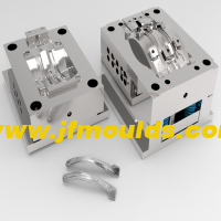
(1) Fixed mold A plate and moving mold B plate open the frame
According to the shape of the four corners of the inner mold insert, there are two ways to open the frame. According to the different accuracy of the open frame, the open frame is divided into a coarse frame and a fine frame. The length and width of the thick frame are 4-6mm smaller than the fine frame, and the depth size is 0.5-1mm smaller. The value of R depends on the depth of the frame.

Bumper mold Manufacturer in China (jfmoulds.com)
(2) Pry mold groove
The function of the prying groove is to facilitate the opening of the mold, which is generally processed on the fixed mold A plate or moving mold B plate and the four corners of the push rod plate.

(3) Code mold slot
The die groove is used for clamping when the mold is installed on the injection molding machine. There are generally four types of mold slots for injection molds.
(4) Top stick hole
The top rod of the injection molding machine pushes the pusher bottom plate and the pusher fixing plate through the K.O hole of the injection mold, and then pushes the plastic part away from the mold by the pushing part. The size and position of the K.O hole of the injection molding machine of different specifications and models are different, and the design should pay attention to the information of the injection molding machine provided by the customer: the specification and model, whether it is imperial or metric, etc. Also, pay attention to whether the customer requests tapping on the thimble base plate.
The general mold is only designed with a top stick hole, which is located in the center of the mold, but when the mold is large and long, the main channel of the mold deviates from the center of the mold is large, or the number of parts pushed up and down the mold is very different, in order to make the push plate push out smoothly, two or more top stick holes are often used.
The top rod of the injection molding machine is usually only responsible for pushing the dry plate, and the repeated position of the push rod plate is done by the return spring and the return bar. However, sometimes the pusher must be reset before closing the mold, at which point the top rod must both push the pusher plate out and pull the pusher plate back, for this purpose the screw hole can be machined on the pusher base plate, the top rod can be fixed on the pusher base plate, or a sleeve with screw holes can be installed on the pusher base plate.

(5) Eye screw hole
The eye screw hole is a screw hole for mold installation. The size of the eye screw hole and the corresponding mold base specifications.
For mold bases with a mold width of less than 300mm, generally only need to process a hole in the eyelet on the top and bottom end of the template. For mold bases with a mold width of more than 300mm, there should be at least one eye screw hole on each side of the formwork. When the length of the formwork base is 2 times or more of the width, two eyescrew holes should be made on each side of the formwork. The position of the eye screw hole should be placed in the center of the edge of each formwork. The depth of the eye screw hole should be at least 1.5 times the diameter of the screw hole, see Table 3-7. The eye screw cannot interfere with other structures such as cooling water pipes and screws, and the main size and safe bearing weight of the eye screw are involved.

(6) Other requirements for the formwork
1. All formwork must be chamfered, and the chamfer size is generally (2~3mm)X45°. All holes on the formwork (including screw holes) must also be chamfered, and the size is generally (0.5~1mm) X45.
2. Under normal circumstances, it is required to leave a gap of 1mm between A and B plates (except for the customer's request not to leave it).
3. The four guide columns must have one eccentric 2mm, except for the two-color material injection mold that needs to rotate 180° for the opposing formwork.
4. The two-color injection mold needs to rotate 180° during the injection process, and the mold base requirements are very high. Special requirements must be made when customizing the mold base, the guide column cannot be eccentric, the position requirements of the straight lock are also particularly strict, and the moving mold bottom plate and the fixing mold panel must be made into a positioning ring, and the positioning ring of the moving mold base plate must be located in the center of the mold base.
5. The top surface of the mold base should be marked with "TOP", each template should be numbered, the reference angle should be marked with "O", and the height of the letter should be generally 10mm.
6. The shape of the mold base requires at least four sides (two reference surfaces and upper and lower surfaces) to be 90° for high-precision and automatic unthreading dies, and all six sides must be 90. , and the accurate positioning between each plate must be ensured.
7. If there is a device protruding from the bottom of the top surface of the mold, there must be a support column on the mold base to protect it.
8. The overall dimensions of the mold base meet the requirements of the drawings, the length and width dimensional tolerance is 0~0.50mm, and the thickness tolerance of each template is 0~0.20mm.
9. The shape of the mold base requires that each plate must be level, and the push rod plate should not protrude outside the mold base.
10. All screw heads are required to sink 1mm, and the screwing length of the screw is at least 2 times the outer diameter of the thread.
11. The size of the moving and fixed mold frame must be consistent, and the position error should be less than 0.03mm.
12. The bottom of the moving and fixed mold frame must be kept flat, and the surrounding step shall not exceed 0.05mm, and the width shall not be greater than 10mm.
13. The reset rod and the moving mold B plate are used as gap fitting, the mating tolerance is H7/f6, and the mating length is 1.5 times the diameter of the reset rod, and other places are empty.
14. If the push rod plate guide column is inserted into the moving template, the insertion depth is 10-15mm, and the air avoidance on one side is 0.1mm.
15. Inspection of new mold base: After receiving the mold base sent from the mold base supplier, the mold department must disassemble and inspect all the molds before processing, find problems, notify the supplier to solve them in time, and inspect them item by item when inspecting the mold base.
Related News
Causes of defects in injection molded products
2025-07-27
Causes of defects in injection molded products The electrical part of the inj...

Focus on quality and deeply cultivate innovation
2025-07-05
Focus on quality and deeply cultivate innovation In daily life, from the mobi...
Solutions to problems such as poor transparency, unstable dimensions, spots, and black lines in injection molded products
2025-07-31
Solutions to problems such as poor transparency, unstable dimensions, spots, and...

Solutions to the problem of easy breakage at the junction of the mold's appearance color difference and material flow
2025-09-05
Solutions to the problem of easy breakage at the junction of the mold's appearan...
Types and basic requirements of mold design drawings
2025-09-07
Types and basic requirements of mold design drawingsTo shorten the production cy...
Exploring Injection Molds: The Precision Foundation of Industrial Manufacturing
2025-07-11
Exploring Injection Molds: The Precision Foundation of Industrial Manufacturing ...